d. SEPARATING HUB AND ROTOR
Raise Hub/Rotor Trolley to the full height position. This is a set position governed by a
limit switch. Raise Service Trolley to match height of locating rod on Hub/Rotor Trolley.
Manoeuvre Hub/Rotor trolley to insert the locating rod into tube on Service Trolley, then
tighten knob to secure (Fig. 10) (Adjust sliding plate on trolley to suit hub if required)
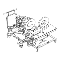
Fig. 10 Hub/Rotor Trolley mated with Service Trolley
Release Red Arms from Face Plate and lower Hydraulic Puller.
Remove bolts securing rotor to hub and then lift Hydraulic Puller into position again and
reattach Red Arm to Face Plate. Fit BLUE Arms to Hydraulic Puller by inserting pin into
hole best suited to hub/rotor distance. (Fig. 11) Position clamp ends of Blue Arms onto
rotor and tighten knobs to secure. (Fig. 12) The hydraulic puller can now be used to push
the rotor/hub assembly apart.
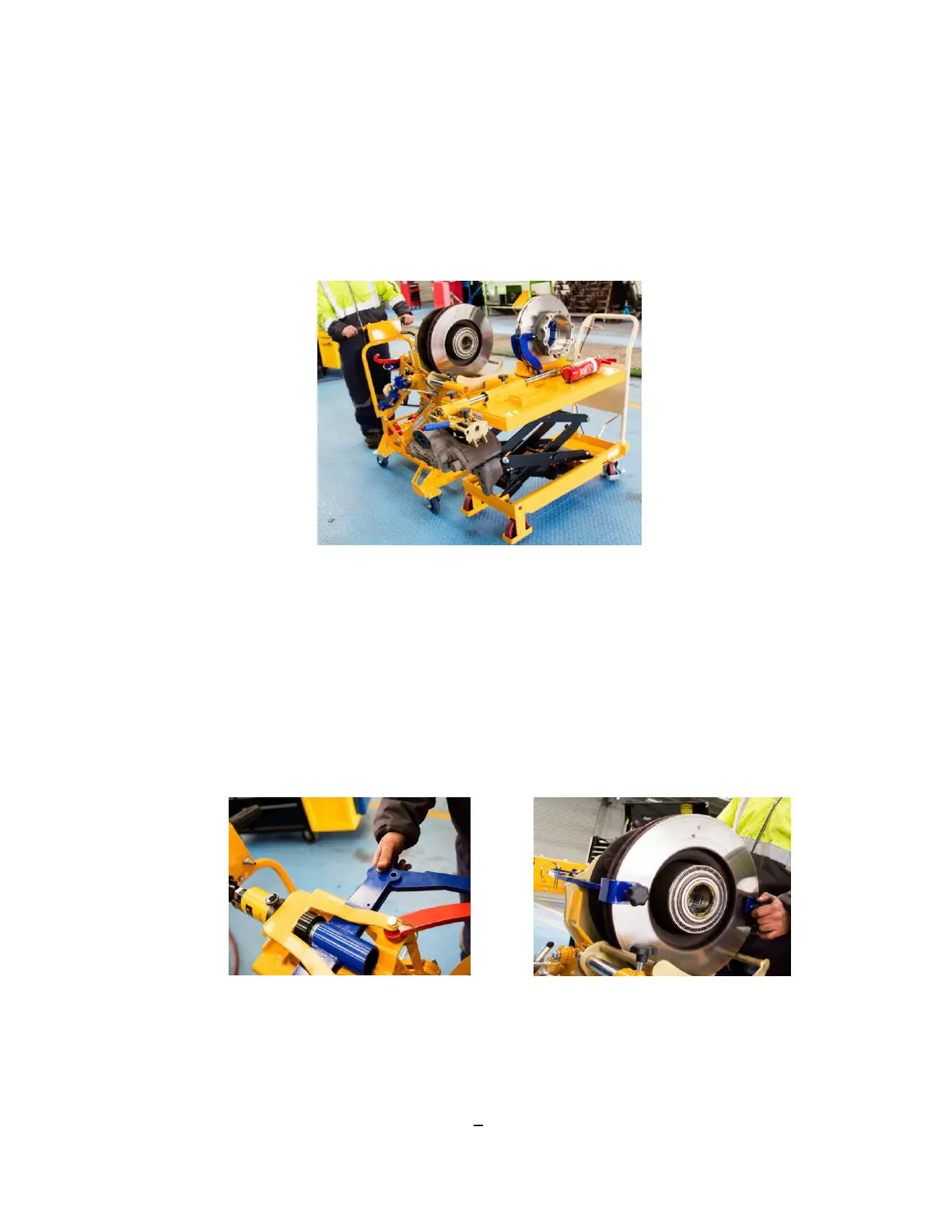
Fig. 11 Fitting Blue Arms Fig. 12 Securing clamps to rotor
9