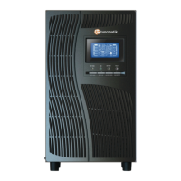
15: Inverter voltage adjustment
Parameter 2: you may choose Add or Sub to adjust inverter
voltage
Parameter 3: the voltage range is from 0V to 9.9V, the default
value is 0V.
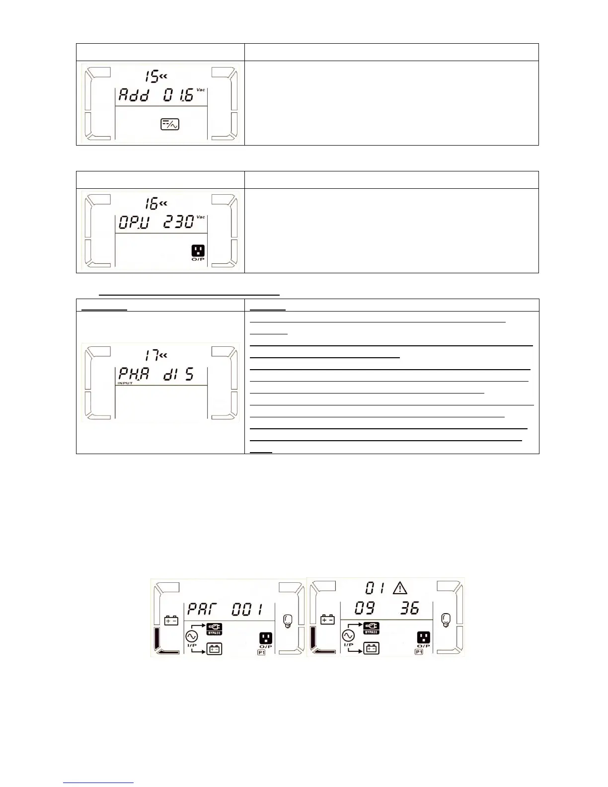
16: Output voltage calibration
Parameter 2: it always shows OP.V as output voltage.
Parameter 3: it shows the internal measurement value of the
output voltage, and you can calibrate it by pressing Up or Down
according to the measurement from an external voltage meter.
The calibration result will be effective by pressing Enter. The
calibration range is limited within +/-9V. This function is normally
used for parallel operation.
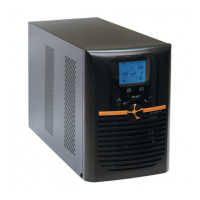
17: Phase auto adapt enable/disable
Parameter 2: it always shows PH.A as phase auto adapt
function.
Parameter 3: Enable or disable phase auto adapt function. You
may choose following two options:
DIS: disable phase auto adapt function. Then, the UPS only can
accept one condition which the phase difference of L2 and L1 is
120º and phase difference between L3 and L2 is 120º.
ENA: enable phase auto adapt function. Then, the UPS can accept
either inputs of L1, L2, L3 in the same phase or the phase
difference between L2 and L1 with 120º, L3 and L2 with 120ºor
phase difference between L2 and L1 240º, and L3 and L2 with
240º.
3-8. Operating Mode/Status Description
Following table shows LCD display for operating modes and status.
(1) If the UPS is in normal operation, it will show four screens one by one, which represents 3 phase input
voltage (L1, L2, L3) and frequency in turns.
(2) If parallel UPS systems are successfully set up, it will show one more screen with “PAR” in parameter 2
and assigned number in parameter 3 as below parallel screen diagram. The master UPS will be default
assigned as “001” and slave UPSs will be assigned as either “002” or “003”. The assigned numbers may be
changed dynamically in the operation;
Parallel screen Warning screen
(3) If some errors occur in the UPS, it will show one more screen to represent the warning situation. In the
warning screen, it can show up to 3 error codes and each code indicates one error. You can find the
meanings of error codes in the warning code table.