user manual
TA-890
TA-890 user manual
Page 49
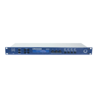
LMS-D6 Rear Panel Functions
1. Power Switch.
2. Mains Fuse - Located in a finger-proof fuseholder adjacent to the mains inlet.
Always replace this fuse with the correct type as shown on the rear panel legend.
(N.B. A spare fuse is located in this holder.)
3. Mains Power - Connected via a standard IEC socket. A compatible power cord is
supplied with the unit.
4. External - RS232 via a 9-pin DIN DEE socket, for connection to a PC.
5. XLR Inputs and Outputs - 3 pin XLR connectors are provided for each audio input
and output. All terminations are fully balanced, pin 2 Hot, pin 3 Cold and pin 1 not
connected.
Mains Power
The LMS-D6 must always be connected to a 3 wire grounded AC supply. It is supplied with a
standard IEC power cord with conductors as follows:
BROWN Power line Live (Phase)
BLUE Power line Neutral
GREEN/YELLOW Safety Earth and ground connection
Units supplied to the North American market are fitted with an integral moulded 3 pin
connector, which is provided to satisfy UL & CSA safety standards.
1 2 3 4 5
INPUT B INPUT A
CUSTOM M AD E F OR TURBOSOUND
IN THE UK BY XTA ELECTRONICS
PROTECTION AGAINST FIRE
REPLACE ONLY WITH THE
SA ME TYP E T1A , 250V FUSE
RS232
DATA INPUT
PIN1=SHIELD
PIN2=HOT
PIN3=COLD
THIS EQUIPMENT MUST BE EARTHED
RISQUE DE CHOC ELECTRIQUE - NE PAS OUVRIR
WARNING / AVIS
OUTPUT 6 OUTPUT 5 OUTPUT 4 OUTPUT 3 OUTPUT 2 OUTPUT 1
DO N OT EX PO SE TO RA IN OR M OI ST URE
SHOCK HA ZARD – DO NOT REM OVE CO VERS
 Loading...