Do you have a question about the Turbosound LMS-D26 and is the answer not in the manual?
The LCD displays preset and parameter information. At start up the display shows the default screen with the memory location and name of the current preset.
Scrolls through available inputs and outputs. Stereo linked channels show association, e.g., 'CH A+B'.
The name of the edit parameter is displayed in the bottom left. Pressing buttons moves through available parameters for current input/output.
Adjusts up to three displayed parameters. Clockwise increases, anti-clockwise decreases value. Rapid turning accelerates action.
LEDs indicate status. Pressing a mute button toggles mute on and off for its associated channel.
Allows users to store setups in 45 memory locations and name presets. Pressing again completes the task.
Do not remove covers, ensure earthing, protect power cord, use specified accessories, refer servicing to qualified personnel.
Product complies with EMC and Low Voltage Directives, conforming to European standards EN60065, EN55103-1, EN55103-2.
Thank you for choosing Turbosound LMS series controller. Read manual for best performance.
Check unit for damage after unpacking. Notify carrier if damage is found. Retain packaging for future re-shipment.
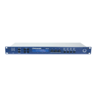
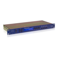
Describes LMS-D24/D26 as state-of-the-art DSP audio processing units combining functions in a 1U rack unit.
Highlights minimal signal path, superb ADC/DAC, SHARC DSP, 96kHz sampling, and front panel controls.
Manual provides detailed descriptions of functions, front/rear panel controls, and features with annotated images.
Set of three LEDs per channel indicate signal present, +4dBu operating level, and input clip.
Controls for accessing 45 presets. Allows naming and selecting memory locations for storing or recalling setups.
Selects input/output channels and utility functions. Displays channel name and pairing for stereo linking.
Edit buttons navigate parameters. Text display shows preset, channel, parameter, and status info on a 2x24 character LCD.
Three velocity-sensitive knobs adjust displayed parameters, linked to screen zones. Turning adjusts values.
Two LEDs per output show signal level relative to limiter threshold (yellow for -6dB, red for threshold reached).
Mute buttons toggle output mute status. Rear Secure Button disables front panel controls for tamper-proofing.
Connects to mains supply. Expansion port is for future network card fitting.
Balanced XLR connectors for audio inputs and outputs. Details wiring and grounding for signal processing.
Serial comms port for PC control and firmware updates. Network port is a future option.
Unit powers on via IEC inlet. Displays firmware info and mutes outputs until internal checks are complete.
Library of 30 presets for Turbosound enclosures. Recall involves pressing the Recall button multiple times.
Utilizes two 'Base Presets' (mono/stereo) for developing custom settings. Edited versions can be stored.
Many processing elements are adjustable parameters. Parameters are adjusted using the three parameter knobs.
Knobs adjust parameters shown in display zones. Turning clockwise increases, anti-clockwise decreases value.
Navigate between channels, utilities, and back to default screen using channel buttons.
Edit buttons access parameter pages for each channel. Scrolling moves through different processing pages.
Select an existing preset by pressing Recall, turning knob A, and confirming. Factory presets are indicated by a box symbol.
Users can develop presets based on factory or basic presets. All parameters can be adjusted.
Press Store button, select location with knob A, name preset with knobs B/C, and press Store again to save.
User can only overwrite non-protected presets. Attempting to overwrite locked presets displays a 'LOCKED PRESET' message.
Diagram showing input signal flow through gain, delay, EQ, and routing stages.
Diagram showing output signal path including delay, filters, EQ, gain, mute, and limiter.
Describes Mono and Stereo formats, including channel pairing for stereo operation.
Adjusts input gain from -80dB to +20dB in 0.2dB steps using parameter knob A.
Adjusts input delay from 0 to 400ms. Velocity-sensitive knobs allow fine or rapid adjustment.
Adjusts HPF frequency (10.0Hz to 25.6kHz) and filter type (Butterworth, Bessel, Linkwitz-Riley, Hardman).
Provides filter slopes up to 4th order or 24dB/octave. Not all types available for all slopes.
Adjusts frequency, slope (6-12dB/octave), and gain (+/-15dB) for shelving EQ sections.
Adjusts centre frequency, width (Q or BW), and gain for six parametric EQ sections.
Adjusts output gain (-80dB to +20dB) and polarity (normal or reversed) for each output channel.
Adjusts output delay from 0 to 80ms. Velocity-sensitive knobs allow fine or rapid adjustment.
Sets LPF frequency (10.0Hz to 25.6kHz) and filter type (Butterworth, Bessel, Linkwitz-Riley, Hardman).
Provides filter slopes up to 8th order or 48dB/octave. Not all types available for all slopes.
Adjusts frequency, slope (6-12dB/octave), and gain (+/-15dB) for output shelving EQ sections.
Adjusts centre frequency, width (Q or BW), and gain for output parametric EQ sections.
Sets the limiter threshold from -40dBu to +20dBu in 0.2dB steps for signal dynamics control.
Configures output source selection (Input A, B, or Sum A+B) for mono format presets.
Adjusts screen contrast and display units for parametric EQ bandwidth (Q or octaves).
Graphs showing magnitude response for Butterworth and Linkwitz-Riley filters at various slopes (dB/Octave).
Graphs showing magnitude response for Bessel filters (dB/Octave) and Hardman filters (Order).
Graphs illustrating shelving EQ response changes with varying gain and slope.
Graphs illustrating parametric EQ response changes with varying gain and bandwidth.
Details inputs, outputs, impedance, levels, sample rate, frequency response, THD, dynamic range, and comms data.
Details gain, filter frequencies, filter types, delay, limiter, EQ specs, and connector types.
Covers mains power, consumption, weight, and physical size (1U rack mount).
One-year warranty against defects in components and workmanship. Specifies return and service procedures.
Excludes defects from unauthorized modifications, misuse, negligence, accidents, or non-compliance with instructions.
| Type | Digital Loudspeaker Management System |
|---|---|
| Input Channels | 2 |
| Output Channels | 6 |
| Sampling Rate | 96 kHz |
| Ethernet Port | Yes |
| USB Port | No |
| A/D Conversion | 24-bit |
| D/A Conversion | 24-bit |
| Power Supply | 100-240V AC, 50-60 Hz |
| Analog Inputs | 2 x XLR |
| Analog Outputs | 6 x XLR |
| Input Impedance | 10 kΩ |
| EQ | Parametric |
| Delay | Yes |
| Limiter | Yes |
| Display | LCD |
| PC Connectivity | Ethernet |
| Processing Delay | 1.5 ms |