7 Commissioning
The device is operational automatically once the cables are connected and the power supply is
switched on.
8 Operation
8.1 LEDs
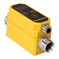
Fig. 5: LEDs 1 and 2
LED Display Meaning
LED 1 Green Positioning element within measuring range
Yellow Positioning element in detection range with reduced signal
quality (e.g. distance to sensor too large)
Yellow flashing Positioning element not in detection range
Off Positioning element outside of set measuring range
LED 2 Green Power supply error-free
9 Setting
The sensor offers the following setting options:
■
Set the start of the measuring range (zero point)
■
Set the end of measuring range (end point)
■
Reset measuring range to factory settings:
maximum measuring range
■
Reset measuring range to inverted factory settings:
maximum measuring range, inverted output characteristic
■
Activate/deactivate Teach Lock
The measuring range can be set by manual bridging or with the TX1-Q20L60 teach adapter.
Zero point and end point of the measuring range can be set in succession or separately.
NOTE
Keep pin 5 potential-free during operation in order to prevent any accidental teach
operations, or activate Teach Lock (see chapter 9.1.4/9.2.4).
LED 2
LED 1
 Loading...