Do you have a question about the turck PS Series and is the answer not in the manual?
These instructions are aimed at qualified personnel and must be carefully read by anyone mounting, commissioning, operating, maintaining, dismantling or disposing of the device.
DANGER, WARNING, CAUTION, NOTICE, NOTE, CALL TO ACTION, and ACTION RESULT symbols with their meanings are explained.
Lists related documents available on www.turck.com, including data sheets and user manuals.
Provides contact information and suggestions for improving the clarity and content of the instructions.
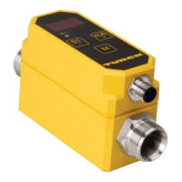
Details on how to identify PS-Series pressure sensors using model codes and parameters.
Information about Turck's support services and access to their product database.
Defines general parameter data used to identify sensors, including IO-Link revision and Device IDs.
Describes how measured values and switching states are mapped in process data (16-bit width).
Details the mapping of measured values using 14 bits, including overflow and underflow conditions.
Provides the formula for calculating pressure from the IOL value for a specific sensor range.
Defines functions for output 1 and 2, including hysteresis and window modes.
Details linear output configurations (mA or V) for the LI2UPN electrical connection.
Defines the behavior of switching outputs, specifying PnP and nPn modes.
Lists supported units for display, including standard and derived units.
Configuration options for measured value update time, display rotation, and menu locking.
Settings for enabling or disabling write protection for IO-Link parameters.
Defines switch and reset points for output 1 and 2, including value constraints.
Specifies the start and end values for the analog range with allowed value constraints.
Allows adjustment of the offset for the sensor's reading, with specified value limits.
Describes the memory for the maximum and minimum recorded values.
Configures the damping time for the analog output signal.
Configures the damping time for the switching output signal.
Sets the switching delay for switch and reset points of output 1 and 2.
| Category | Accessories |
|---|---|
| Output voltage | 24 VDC |
| Protection class | IP20 |
| Protection | Short-circuit, Overload, Overvoltage |
| Product type | Power Supply |
| Output current | 20 A |
| Approvals | CE, cUL |
| Mounting | DIN rail |
| Series | PS Series |