2-52-4
Mechanical InstallationMechanical Installation
Copyright © 2021 ves.co | All Rights Reserved Copyright © 2021 ves.co | All Rights Reserved
Outlet Guard
Recommended Tools
Bit (#2)
10mm
Li/Ladder if applicable
Installation Steps
Rough Opening Verication
Prior to install, verify the rough opening is accurate for
the corresponding fan model. See “PPF Rough Open-
ing” on page 2-1 for details.
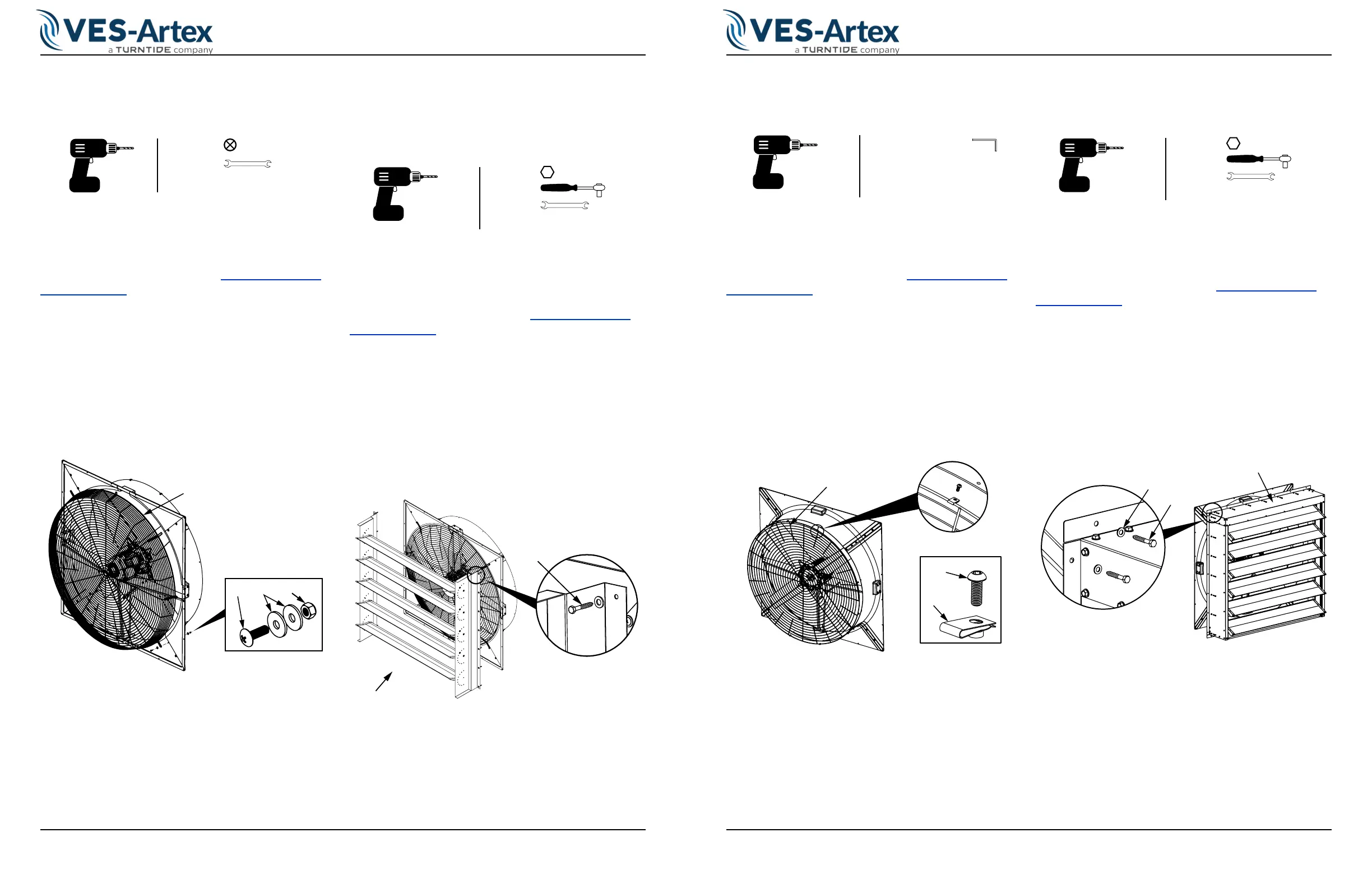
1. Install screw (B) and washer (C) through wire loop
of guard partially into the top left corner of the fan.
See
Figure 2-3.
2. Place the guard (A) onto squared ange. Be sure
guard (A) is centered and squared to the opening.
3. Install top left screw (B), washers (C) and nut (D).
4. Install remaining screws, washers nuts (B) around
guard (A) to secure.
B
C
D
A
Figure 2-3. Outlet Guard
Inside Deector Kit (IDK)
Recommended Tools
13mm
13mm
13mm
Li/Ladder if applicable
Installation Steps
Rough Opening Verication
Prior to install, verify the rough opening is accurate for
the corresponding fan model. See “PPF Rough Open-
ing” on page 2-1 for details.
1. Install screw (B) through deector (A) partially into
the top left corner of the fan. See
Figure 2-4.
2. Place the deector (A) onto squared ange. Be
sure deector (A) is centered and squared to the
opening.
3. Install top right screw (B) fully into the framework.
4. Install remaining screws and anged washers (B)
through deector (A) to secure.
B
A
Figure 2-4. Inside Deector
Inlet Guard
Recommended Tools
4mm hex key or bit
Li/Ladder if applicable
Installation Steps
Rough Opening Verication
Prior to install, verify the rough opening is accurate for
the corresponding fan model. See “PPF Rough Open-
ing” on page 2-1 for details.
1. Install screw (B) and clip (C) around wire loop of
guard partially into the top of the fan. See
Figure
2-5.
2. Place the guard (A) onto squared ange. Be sure
guard (A) is centered and squared to the opening.
3. Install top screw (B) and clip (C).
4. Install remaining screws (B) and clips (C) around
guard (A) to secure.
A
C
B
Figure 2-5. Inlet Guard
Actuated Shutter Kit (ASK)
Recommended Tools
13mm
13mm
13mm
Li/Ladder if applicable
Installation Steps
Rough Opening Verication
Prior to install, verify the rough opening is accurate for
the corresponding fan model. See “PPF Rough Open-
ing” on page 2-1 for details.
1. Install screw (B) and washer (C) partially into the
top left corner of the fan. See
Figure 2-6.
2. Place the Shutter (A) onto squared ange. Be sure
shutter (A) is centered and squared to the opening.
3. Install top right screw (B) fully into the framework.
4. Install remaining screws (B) and washers (C) around
shutter (A) to secure.
A
B
C
Figure 2-6. Shutter