Service Manual 73
Page 10 of 32
REMOVE THE COVER GASKET:
If a new gasket is not available, reuse of the original gasket is acceptable, provided it is not
torn or otherwise damaged.
REMOVE THE IDLER FROM THE PIN:
With the idler gear still on the cover, check for excessive wear between:
− the pin and bushing,
− the idler and cover crescent,
− idler width and crescent height.
Any visible signs of excessive wear will require replacement of the cover/pin assembly
and/or the idler and the bushing.
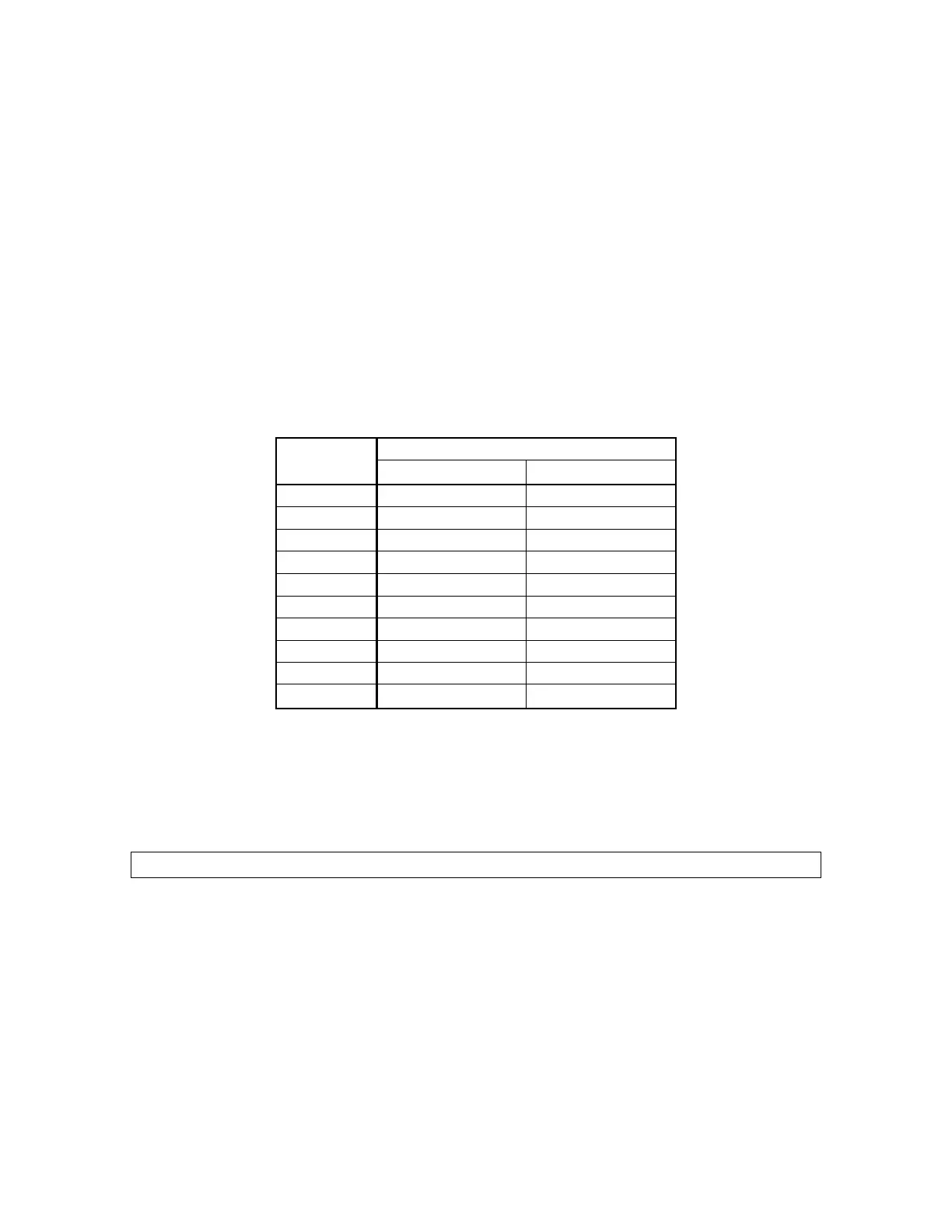
If only the bushing shows signs of minor wear, it should be replaced. Acceptable bushing
clearances are shown in Table 3 (for pumps with standard clearance only)
Acceptable Clearance
Pump Size
inch mm
GG015 0.001 -0.007 0.038 -0.178
GG030 0.001 -0.007 0.038 -0.178
GG050 0.002 -0.008 0.051 -0.203
GG070 0.002 -0.008 0.051 -0.203
GG080 0.002 -0.008 0.051 -0.203
GG090 0.002 -0.008 0.051 -0.203
GG120 0.002 -0.009 0.064 -0.229
GG130 0.002 -0.009 0.064 -0.229
GG200 0.003 -0.009 0.089 -0.229
GG210 0.003 -0.009 0.089 -0.229
Table 3 - Idler Bushing Clearances
Note: Many Tuthill pumps are provided with non-standard clearances for use with high-
viscosity or high-temperature fluids. Consult the factory for clearances of these pumps.
Drive Module Removal
REMOVE THE DRIVE MODULE ASSEMBLY FROM HOUSING:
If service is being completed with the housing still mounted to the baseplate/piping, you must first
remove the spacer from the spacer coupling.
Adequately support the housing ( on the cover side) so it will not fall.
Remove the bolts that hold the bracket to the housing.
On pumps that do not have a cast integral foot, remove the bolts that attach the foot to the
bearing carrier.
 Loading...