20
05 Menu Operations
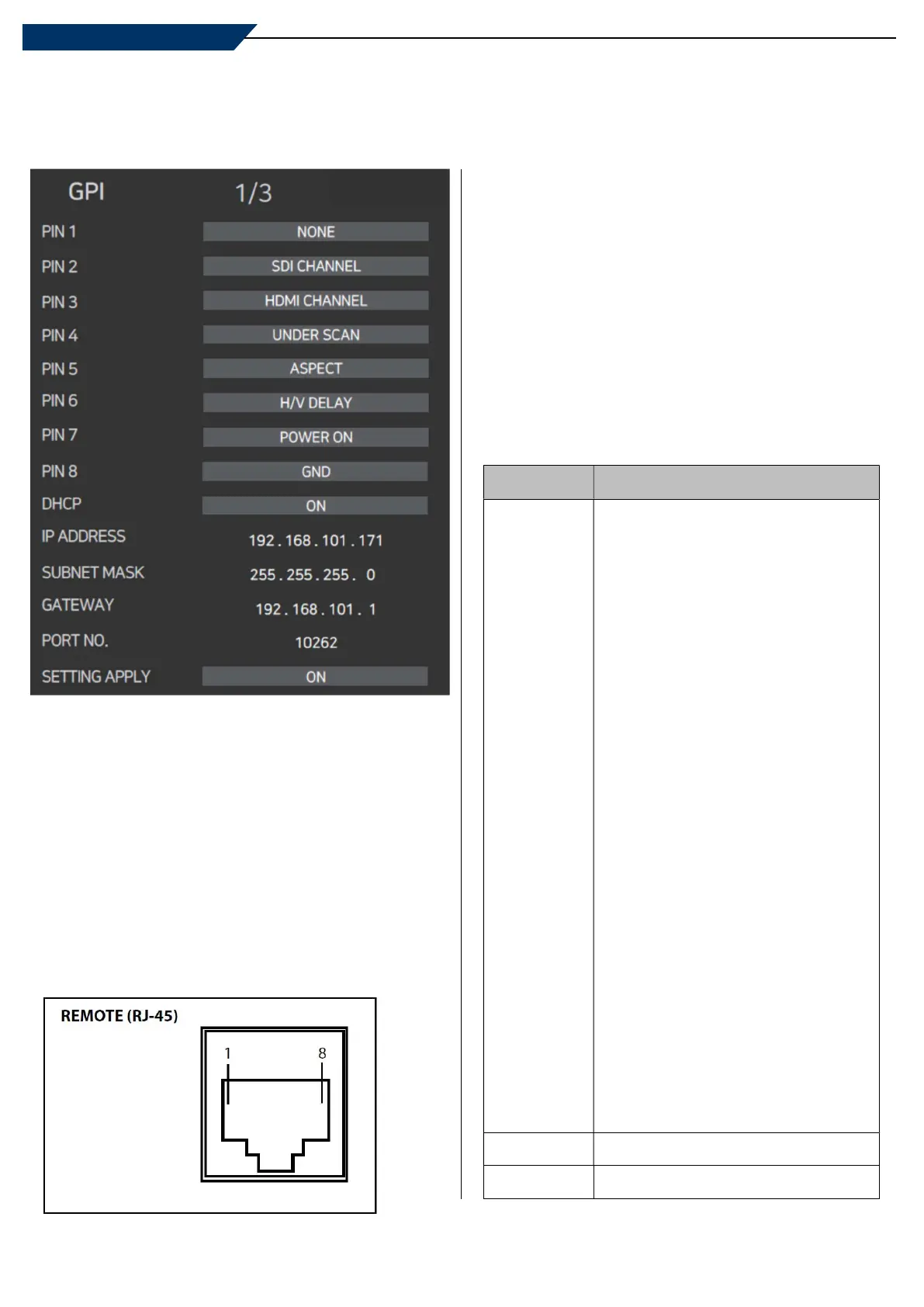
[4] GPI
GPI PIN 1 ~ PIN 8
- This item activates/deactivates the REMOTE function.
- The user may connect an RJ-45 jack to the REMOTE
terminal on the rear of the unit and designate a function
for each pin.
- The default settings are as follows :
PIN1 : NONE / PIN2 : NONE / PIN3 : NONE
PIN4 : NONE / PIN5 : NONE / PIN6: NONE
PIN 7 is POWER ON/OFF use only and PIN 8 is GND.
- The selectable values are as shown on the Right.
The pin positions are as follows :
DHCP
- Used to set DHCP.
IP ADDRESS / SUBNET MASK / GATEWAY
- Used to set the Network address.
PORT NO
- Used to set the port number. The default value is [10262].
SETTING APPLY
- Used to apply the settings.
PIN NO. Settable Values
PIN
1~6
NONE
SDI A CHANNEL
SDI B CHANNEL
PBP CHANNEL
HDMI CHANNEL
COMPOSITE 1 CHANNEL
COMPOSITE 2 CHANNEL
COMPOSITE 3 CHANNEL
COMPONENT CHANNEL
RGB CHANNEL, DVI CHANNEL
1:1 SCAN, ASPECT
H/V DELAY, BLUE ONLY, MONO
16:9 MARKER, 4:3 MARKER
4:3 ON AIR MARKER
15:9 MARKER, 14:9 MARKER
13:9 MARKER, 1.85:1 MARKER
2.35:1 MARKER
1.85:1 & 4:3 MARKER
CENTER MARKER
SAFETY AREA 80%
SAFETY AREA 85%
SAFETY AREA 88%
SAFETY AREA 90%
SAFETY AREA 93%
SAFETY AREA 100%
TALLY R, TALLY G
PIN 7
POWER ON/OFF CONTROL
PIN 8
GND
Multi Format LCD Monitor
2: PIN 2
3: PIN 3
4: PIN 4
5: PIN 5
6: PIN 6
7: PIN 7

 Loading...