Rebar Scanner A60+
12
Press ← and →keys to move the cursor and press ↑ and ↓keys to
adjust the value of cursor position. After above setting is end, press the
ENTER key to confirm the setting. Then probe is self-calibrated. At
this time, probe should be placed in the air and away from the strong
magnetic field interference. At the same time, wait! is showed on the
screen. After wait!is missing, it indicates self-calibration of probe is
end. At this time, enter into detection status.
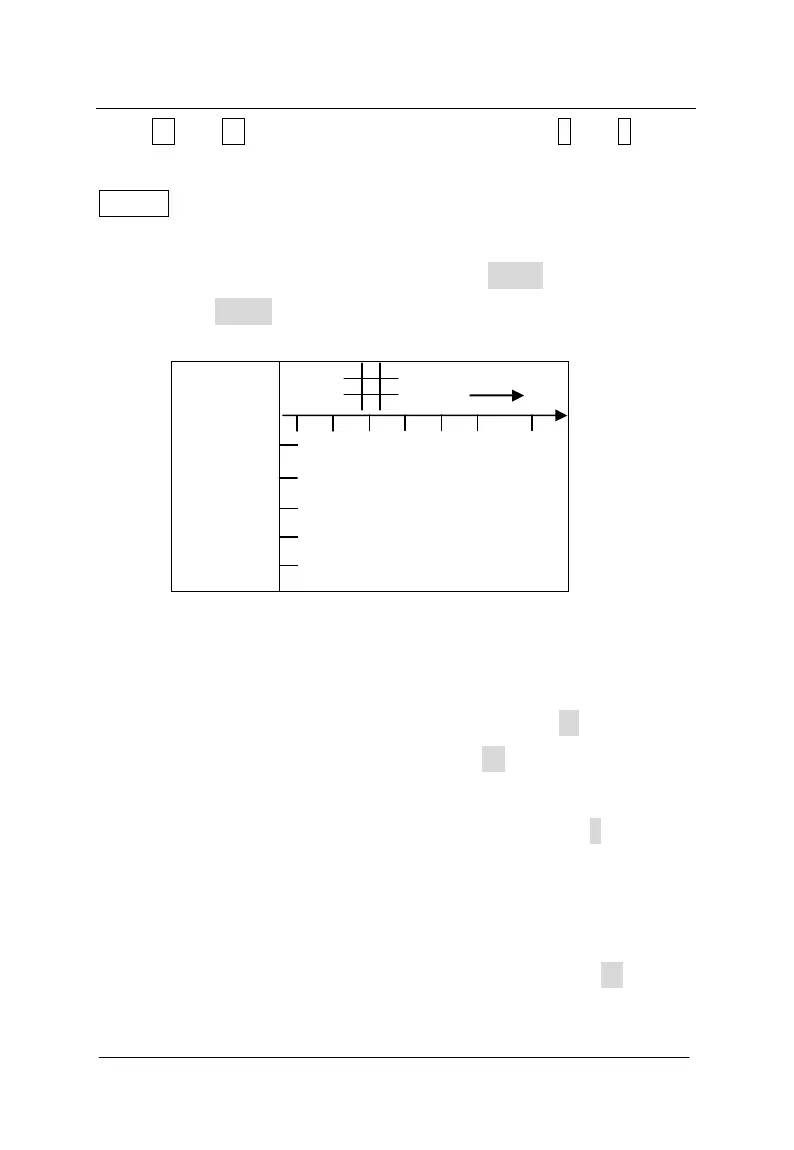
X ø16mm
Y ø08mm
3000
D
T
0.5
m
Figure 3-9 interface of 0.5×0.5m grid scan
There is one wheel and the plug on the positive direction of the
trolley. During detection, the trolley only forwards the positive
direction. During going forward, the number under the D is increased.
During detection, the number under the D is horizontal distance
that the probe is relative to the zero point. Unit is mm. Current
covering layer thickness of rebar is showed under the T. Scanning
direction of trolley is showed on the right upper corner. According to
design data or experience, direction of rebar is determined. If direction
of rebar is not determined, position of rebar will be determined
according to detection method of rebar. According to → shown,
longitudinal rebar of grid pattern is detected. Detected point should