Rebar Scanner A60+
16
X ø16mm
No.
4000
D
T
·
0.5
m
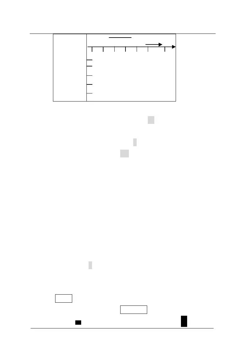
Figure 3-11 0.5m scanning interface of section plane rebar
During detection, the number under the D is the distance that the
probe is relative to the zero point. Unit is mm. Current covering layer
thickness of rebar is showed under the T. Scanning direction of trolley
is showed on the right side of D. According to design data or
experience, direction of rebar is determined. If direction of rebar is not
determined, position and direction of rebar will be determined
according to detection method of rebar. The trolley held by hand is
moved horizontally from the left to the right (the probe is parallel to
direction of rebar) and the speed is not more than 20mm/s. (At the
same time, one black block shown on the screen is moved horizontally
from the left to the right.) After hearing the alarm, it indicates there is
rebar under the probe and rebar is showed on the screen in the
formation of black block. At the same time, covering layer thickness is
showed under the T. During continuing to move the trolley
horizontally, when horizontal length that the trolley moves is not less
than 500, it is prompted by means of continuous alarm. At this time,
press the SAVE key to save the data.
During detection, press the RANGE key to switch the first