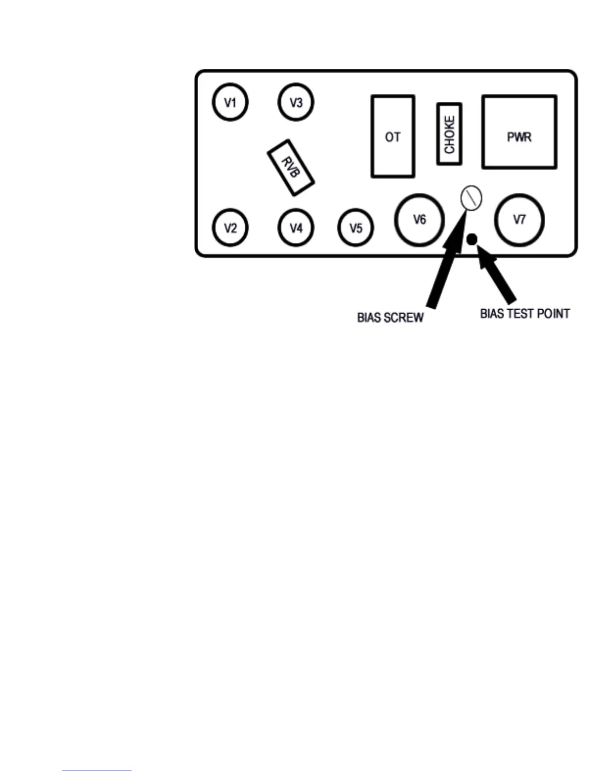
Each ne production tube is tested and matched to our exacting specications. External bias adjust-
ment and test points are located on the chassis near the output tube sockets. A digital voltmeter and
small screwdriver are required for bias adjustment.
BIAS ADJUSTMENTS:
Power up unit and connect proper speaker load.
Set master volumes and effects return controls to zero.
DO NOT apply any signal to the input during the biasing procedure!
Take unit off standby and allow a few seconds for the circuit to stabilize.
Set voltmeter to Millivolt scale (or lowest volt scale 60 millivolts=.060 volts.)
With meter grounded to chassis and + probe at test point, measure voltage.
For other tube types (5881, 6550, EL34) check with the manufacturer or contact us for recommenda-
tions.
Settings higher than 65 mV (.065 Volts) with 6L6 tubes may cause premature tube wear and possibly
damage the amplier.
Keep in mind that tubes vary in quality, and some tubes can handle upwards of 40 mV each (a read-
ing at the test point of 80 mV (0.80 Volts.) However, to be on the safe side, use the above as a guide.
WARNING! No user serviceable parts inside! Refer to qualied service person only.
LINE CORD- For your safety, connect to grounded A/C receptacle only.
Tube Complement
V1- 12AX7, 1st Stage Reverb
V2- 12AX7, Pre Amp
V3- 12AT7, Reverb Drive
V4- 12AX7- FX/Reverb RTN
V5- 12AX7, Phase Inverter
V6-V7 - 6L6 or 6V6 Power
All Fuses are 3AG Type 250 Volt, SLO-BLO
Fuse Chart