EN
Know Your CNC Machine
4
Set up TTC450 Pro
5
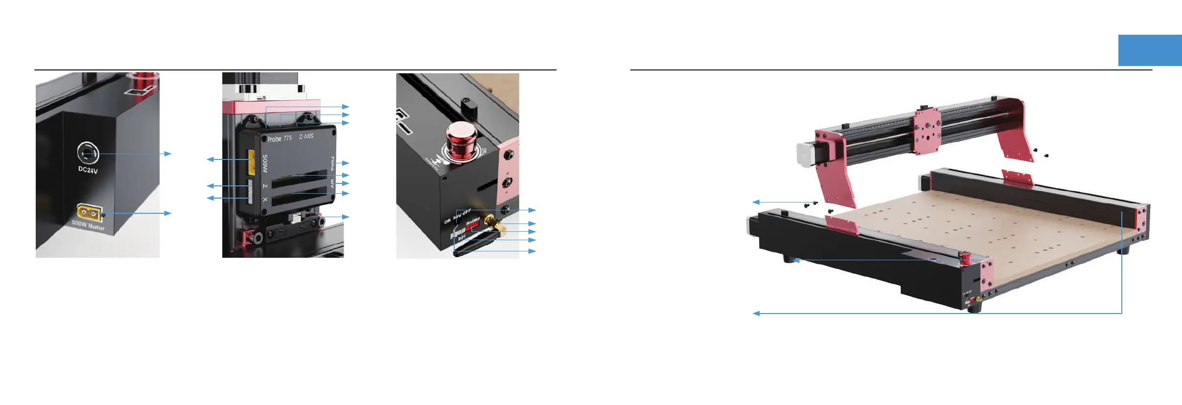
1. DC power interface
2. 500W spindle input
3. 500W spindle output
4. Z-axis Limit signal input
5. X-axis Limit signal input
6. Probe signal input
7. 775 Spindle motor output
8. Z-axis motor output
9. Power input port (M)
10. Signal output port (S)
11. Laser output (PWM)
12. Air pump output
13. X-axis Limit switch
14. 24V Switch
15. 24V Output
16. 24V Triggering signal
17. A-axis
18. Antenna
①
③
⑥
④
⑤
⑦
⑧
⑪
⑨
⑩
⑫
⑬
⑭
⑱
⑯
⑮
⑰
②
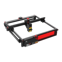
Required parts
X-axis components
M5X8 screw *6
3.0 hexagonal wrench
4.0 hexagonal wrench
Insert the X-axis assembly into
the base and lock it with M5X8
screws.
Step 1 :Installing X-axis components
Install the two screws back with
the XY axis not perpendicular,
and move the Y axis on both
sides to hit the screws to
complete the calibration.
Calibrate the Y-axis (Note: This machine
has been calibrated before leaving the factory).