EasyManua.ls Logo

Tyco Electronics AMP Series User Manual

Default Icon
12 pages
To Next Page IconTo Next Page
Page #1 background imageLoading...
Page #1 background image
1 de 12
Tyco Electronics France SAS, B.P. 30039 95301 CERGY-PONTOISE Cedex Tél. : 01 34 20 88 88 Fax : 01 34 20 86 00
Ce document géré par Tyco Electronics France est archivé dans la base de donnée Startec.
Une impression ne peut être considérée comme un document contrôlé.
This document, managed by Tyco Electronics France, is archived in the Startec database.
A printout cannot be considered as a controlled document.
Préconisation d’utilisation
CONNECTEURS 31 VOIES MT/SPT
Recommendations for utilization
31-WAY MT/SPT CONNECTORS
411-15599
26 Janvier 06 Rév. D
SOMMAIRE
1. INTRODUCTION
2. RÉFÉRENCE ET DESCRIPTION DES
PRODUITS
2.1. Produits plastiques
2.2. Contacts
3. SPÉCIFICATIONS
3.1. Spécifications produits
3.2. Opération de sertissage des contacts
3.3. Instructions de démontage des contacts
4. RECOMMANDATIONS PARTICULIÈRES DU
PRODUIT
4.1. Câblage du connecteur
4.1.1 Mise en place des contacts
4.1.2 Mise en place des verrous secondaires
4.1.3 Mise en place du faisceau et capot horizontal
4.1.4 Mise en place du faisceau et capot vertical
4.2. Mise en place du connecteur
4.3. Démontage du connecteur
4.4. Démontage du capot
5. RECOMMANDATIONS PARTICULIÈRES DE
DÉMONTAGE
5.1. Contacts
5.2. Joint axial
6. RECOMMANDATIONS GÉNÉRALES
D’UTILISATION DES CONTACTS
7. RECOMMANDATIONS GÉNÉRALES
D’UTILISATION DES CONNECTEURS
8. PRÉCONISATIONS POUR LA VALIDATION
DE L’ÉQUIPEMENT DE CONTROLE
CABLAGE PAR PUSH-TEST
CONTENTS
1. IINTRODUCTION
2. PRODUCT REFERENCES AND DESCRIP-
TION
2.1. Plastic products
2.2. Contacts
3. SPECIFICATIONS
3.1. Product specifications
3.2. Contact crimping operations
3.3. Contact removal instructions
4. SPECIAL RECOMMENDATIONS REGAR-
DING PRODUCT
4.1. Wiring the connector
4.1.1 Fitting the contacts
4.1.2 Fitting the secondary latches
4.1.3 Fitting the cable bundle and horizontal cover
4.1.4 Fitting the cable bundle and vertical cover
4.2. Fitting the connector
4.3. Removing the connector
4.4. Removing the cover
5. SPECIAL RECOMMENDATIONS FOR
REMOVAL
5.1. Contacts
5.2. Axial seal
6. GENERAL RECOMMENDATIONS FOR
UTILIZATION OF CONTACTS
7. GENERAL RECOMMENDATIONS FOR
UTILIZATION OF CONNECTORS
8. INSTRUCTIONS FOR VALIDATION OF
WIRING PUSH-TEST EQUIPMENT
Question and Answer IconNeed help?

Do you have a question about the Tyco Electronics AMP Series and is the answer not in the manual?

Tyco Electronics AMP Series Specifications

General IconGeneral
CategoryCables and Connectors
ManufacturerTyco Electronics
SeriesAMP
Connector TypeVaries by specific part number within the series (e.g., Rectangular, Circular, D-Sub, etc.)
Contact MaterialVaries by specific part number within the series (e.g., Brass, Phosphor Bronze, Copper Alloy, etc.)
Contact PlatingVaries by specific part number within the series (e.g., Gold, Tin, Nickel, Silver, etc.)
Voltage RatingVaries by specific part number within the series
Current RatingVaries by specific part number within the series
Operating TemperatureVaries by specific part number within the series
Insulation MaterialVaries by specific part number within the series (e.g., PVC, Nylon, Polypropylene, etc.)
Wire Gauge RangeVaries by specific part number within the series

Summary

INTRODUCTION

PRODUCT REFERENCES AND DESCRIPTION

Plastic products

Details on the plastic components, pre-assembled parts, and secondary latches for the 31-way MT/SPT connector.

Contacts

References for contacts and seals, including specifications for wire gauges and types.

SPECIFICATIONS

Product specifications

Provides specifications for the 31-way MT/SPT connector, Standard Power Timer contacts, Micro Timer 2 contacts, and interface.

Contact crimping operations

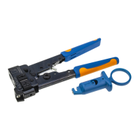
Details the procedures and tooling for crimping contacts, including specific precautions for 1mm² wire.

Contact removal instructions

Instructions and tools for removing receptacles from the connector.

SPECIAL RECOMMENDATIONS REGARDING PRODUCT

Wiring the connector

Steps for fitting contacts into the connector cavities.

Fitting the secondary latches

Instructions for inserting and fully seating secondary latches into their respective keyways.

Fitting the loop and horizontal cover

Steps for routing the cable and fitting the horizontal cover, including cable clamp placement.

Fitting the cable bundle and vertical cover

Steps for routing the cable and fitting the vertical half covers, including cable clamp placement.

Fitting the connector

Instructions for connecting the connector to the header, including opening and closing the bail lock.

Removing the connector

Procedure to disengage and withdraw the connector using the bail lock.

Removing the cap

Steps to remove the connector cap by cutting the cable clamp and releasing retaining catches.

SPECIAL RECOMMENDATIONS FOR REMOVAL

Contacts

Procedure to remove the connector cap and proceed with contact removal as per technical manual.

Axial seal

States that the axial seal must not be removed; replace the connector if faulty.

GENERAL RECOMMENDATIONS FOR UTILIZATION OF CONTACTS

GENERAL RECOMMENDATIONS FOR UTILIZATION OF CONNECTORS

INSTRUCTIONS FOR VALIDATION OF WIRING PUSH-TEST EQUIPMENT

Related product manuals