EasyManua.ls Logo

Tyco 801AP MX User Manual

Tyco 801AP MX
10 pages
To Next Page IconTo Next Page
Page #1 background imageLoading...
Page #1 background image
© 2007 Tyco Safety Products PAGE 1 of 10
801AP
17A-05-AP
4 8/07
EQUIPMENT:
PUBLICATION:
ISSUE No. & DATE:
Fig. 1 801AP MX Service Tool
801AP MX SERVICE TOOL
USER INSTRUCTIONS
1. INTRODUCTION
The 801AP MX Service Tool is used to program the loop address
into MX addressable devices. (A Quick Functional Reference
Table is detailed on page 9).
The 801AP displays information and performs tests on devices.
It has a 32 character backlit LCD alphanumeric display, arranged
in 2 rows of 16 characters and four ‘softkeys’, F1, F2, F3 and F4.
(The display format is shown in Fig. 5).
Power for the 801AP is derived from 4 AA size nickel metal
hydride rechargeable batteries. It may be run from an unregulated
+12V dc input, ie, car cigarette lighter connection or 110/230V
ac mains adaptor, both of which will recharge the batteries as
well. The 801AP consists of the following:
MX Service Tool
Service Tool to ancillary connector lead
110 or 230V ac adaptor plus lead
4 x rechargeable AA size Nickel Metal Hydride
batteries
The 801AP is designed to be used as a desktop unit, clipped to a
trouser belt or be carried with a shoulder strap. The 801AP has
four external connections:
DC IN +12V From car cigarette lighter or
110/230V ac mains adaptor
AUX Ancillary connection port
PC PC connection port for use with
MX CONSYS (not yet available)
μP Internal micro-processor program
download port for use with PMS -
Program Management Software.
Detectors are programmed by placing the detector onto the
801AP and turning clockwise until fully engaged.
Ancillaries are programmed via the AUX port on the 801AP.
The ancillary programming cable consists of an RJ11
connector at one end and a custom moulded connector at the
other end.
2. TECHNICAL SPECIFICATION
2.1 MECHANICAL
Dimensions
HWD: 48 x 200 x 112mm
Weight
801AP Service Tool: 0.36kg
801AP Service Tool + batteries: 0.5kg
Materials
Top: FR ABS Dark Blue
Bottom: FR ABS Dark Blue
www.acornfiresecurity.com
Question and Answer IconNeed help?

Do you have a question about the Tyco 801AP MX and is the answer not in the manual?

Tyco 801AP MX Specifications

General IconGeneral
BrandTyco
Model801AP MX
CategoryMeasuring Instruments
LanguageEnglish

Summary

Introduction to the 801AP MX Service Tool

Service Tool Overview and Capabilities

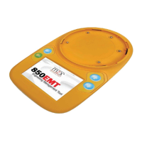
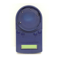
Introduces the 801AP MX Service Tool, its display, and primary functions.

Powering the 801AP Service Tool

Details power sources (batteries, DC input) and charging.

External Connections and Ports

Describes the four external connection ports available on the unit.

Technical Specifications of the 801AP

Mechanical and Physical Attributes

Covers dimensions, weight, and materials of the 801AP Service Tool.

Electrical Specifications

Battery Type and Operating Time

Details battery type, quantity, and expected operating duration.

Environmental Operating Conditions

Temperature and Humidity Limits

Specifies operating/storage temperatures and relative humidity limits.

EMC Compliance Details

EMC Directive Compliance Statement

States compliance with the EU EMC Directive 89/336/EEC.

Operating the 801AP Service Tool

Essential Setup and Safety Guidelines

Crucial initial charging, recharging, and safety warnings for operation.

Starting Up the 801AP Tool

Installing and Changing Batteries

Step-by-step instructions for battery installation and replacement.

Charging the Device via Mains

Explains the process of charging batteries using the mains adaptor.

Password Protection Features

Password Entry and Security Protocols

Details the 6-digit password requirement and its importance for operation.

Connecting to Devices

Device Connection and Password Entry

How to connect detectors and ancillaries after entering the password.

Password Attempt Warnings and Expiry

Critical warnings on password attempts, tool lockout, and expiry.

Button Operations and Navigation

Main Menu Display and Button Mapping

Describes the main menu display and how softkeys map to options.

Model Differences in Communication

Highlights differences in communication priority between older and newer models.

Ancillary Device Connection Notes

Discusses operational notes and potential issues with ancillary connections.

Crucial Safety for Addressable Loop Connection

Preventing Unwanted Actions on Loop

Emphasizes taking special care when connecting to devices on the addressable loop.

Core Functionality of the 801AP

Address Programming and Management

Details reading/writing device addresses and managing programmed address maps.

Viewing Analogue Values and Memory

How to view analogue values and clear the memory map of programmed addresses.

Measuring Temperature

Temperature Measurement Feature

Describes measuring temperature in C and F for specific detectors.

Measuring CO Levels

CO Level Measurement for Detectors

Explains measuring CO levels in the environment for CO detectors.

Performing Comprehensive Tests

Full Detector Test Procedure

Details the combined test for detector terminals and sensor circuitry.

Detector Dirtiness Indicator

Optical Chamber Contamination Level

Explains the dirtiness indicator for optical detectors.

Device Type Identification

Retrieving Device Type Values

Describes how to display unique device type identification values.

Digital Input Status

Displaying Digital Input Status

Explains how to display digital input status in binary and decimal.

Digital Output Control

Setting Addressable Device Outputs

Describes how to set digital outputs for addressable devices.

Critical Safety for Ancillary Device Use

Making Attached Equipment Safe

Crucial safety warning for using the tool with ancillary devices on the loop.

Customer Code Configuration

Customer Code Setting Caution

Caution regarding changing the service tool's customer code for debugging.

Additional Tool Functions

Polling, Battery, and Display Features

Covers device polling intervals, low battery indicator, and LCD backlight.

Automatic Power Off Feature

Details the automatic power-off feature to conserve battery life.

CPU Reset Procedure

Resetting the Service Tool

Describes how to reset the service tool if it becomes unresponsive.

Intrinsically Safe 800Ex Detectors

Programming Requirements for Ex Detectors

Explains programming requirements for Intrinsically Safe 800Ex detectors.

Safe Area Usage for Ex Devices

Safety requirement for using the tool with Ex devices in a non-hazardous safe area.

Programming Lead Compatibility

Compatibility with Different Leads

Details compatibility with different programming leads for newer hardware versions.

Accessories and Spares

Accessory Kit and Spare Parts Listing

Lists items included in the accessory kit and available spare parts.

Main Menu Functionality Reference

Address Programming Function

Read/Writes the address of the connected addressable device.

Analogue Values Display

Displays the analogue values of the addressable device.

Temperature Measurement Function

Measures temperature in degrees C and F.

CO Level Measurement Function

Gives values for CO levels for CO detectors.

All Detector Tests

Performs self-test, remote indicator, and interface tests.

Dirtiness Indicator Function

Indicates optical chamber contamination level as a percentage.

Device Type Identification

Displays the device type identification value.

Digital Inputs Status Display

Displays the status of digital inputs in addressable devices.

Digital Outputs Setting

Allows the user to set digital outputs of addressable devices.

Customer Code Setting

Not normally used, set to match customer code in device.

Low Battery Indicator

Indicates Low Battery by a flashing symbol.

CPU Reset Functionality

Switch accessed through a small hole for reset.

LCD Backlight Activation

Display can be temporarily illuminated by pressing two buttons.

Related product manuals