8
Internet Alarm Communicator Installation Manual
indoor locations only. This manual shall be used with the installation manual of the panel which is
connected to the Ethernet communicator. All instructions specified within the panel manual must
be observed.
All the local rules imposed by local electrical codes shall be observed and respected during instal-
lation.
Installing the Ethernet Cable
A Category 5 (CAT 5) Ethernet cable must be run from a source with Ethernet/Internet connectiv-
ity to the communicator module, inside the panel. The communicator end of the cable must be ter-
minated with an RJ45 plug, which will connect to the communicator’s RJ45 jack after the
communicator is installed. All requirements for installation of CAT 5 Ethernet cable must be
observed for correct operation of the communicator, including, but not limited to, the following:
• Do NOT strip off cable sheathing more than required for proper termination.
• Do NOT kink/knot cable.
• Do NOT crush cable with cable ties.
• Do NOT untwist CAT 5 pairs more than ½ in. (1.2cm).
• Do NOT splice cable.
• Do NOT bend cable at right angles or make any other sharp bends.
NOTE: CAT 5 specification requires that any cable bend must have a minimum 2 in. (5 cm) bend
radius. Maximum length of CAT 5 cable is 328 ft. (100 m).
Running the RS-422 Cable (R models only)
When installing the communicator for use with 3rd party applications an RS-422 cable must be
connected between the 3rd party device and the communicator module.
NOTE: Maximum cable length for RS-422 cable is 1,000 ft. (305 m).
Please refer to the installation manual of the 3rd party device for wiring instructions.
Installing Communicator with HS2016, HS2032, HS2064, and
HS2128 Panel
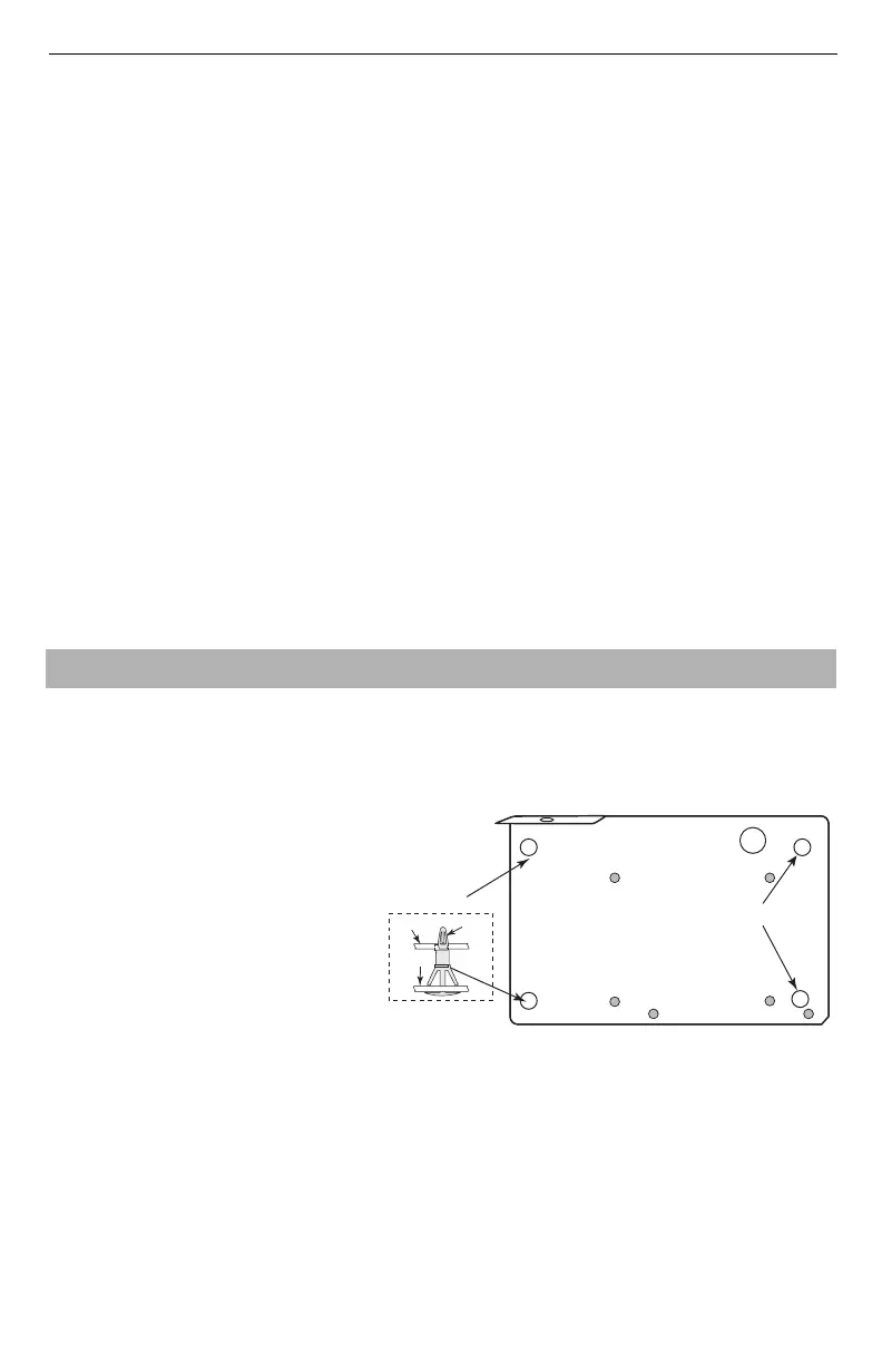
1. To assemble supplied mounting bracket, perform the following: (See
Figure 1
).
a. Remove the 4 white plastic
standoffs from the bag provided
with the communicator kit.
b. Insert the 4 standoffs through the
back of the mounting bracket,
into the holes at each corner.
c. Place the bracket on a flat, solid
surface. Hold the communicator
component side up and orient the
4 holes on the communicator
with the 4 standoffs protruding
from the bracket. Push the com-
municator firmly and evenly onto
the standoffs until it is securely attached to the mounting bracket.
d. Remove the panel front cover.
e. Remove and discard the circular knockout located in the top-right section of the panel.
2. Install the Communicator into the panel:
a. Attach one end of the PC-LINK cable to the PCLINK_2 header on the panel (red wire goes
on the right-hand pin of the panel PCLINK_2 header (see Figure 3)).
b. Insert the assembled communicator into the panel.
INSTALLING ETHERNET COMMUNICATOR IN PANEL
Mounting
Holes
Mounting Holes
Mounting Plate
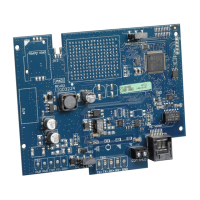
Communicator
Board
Mounting
Plate
Stand Off
Figure 1:Communicator Mounting Bracket