iSTAR Ultra G2 Controller Installation and Configuration Guide 5
■ Built-in LEDs indicate the Ethernet Link and Receive Data signals.
Encryption
■ TLS v1.3 encryption in iSTAR Ultra G2 mode.
■ TLS v1.2 encryption and unencrypted option in iSTAR Ultra mode.
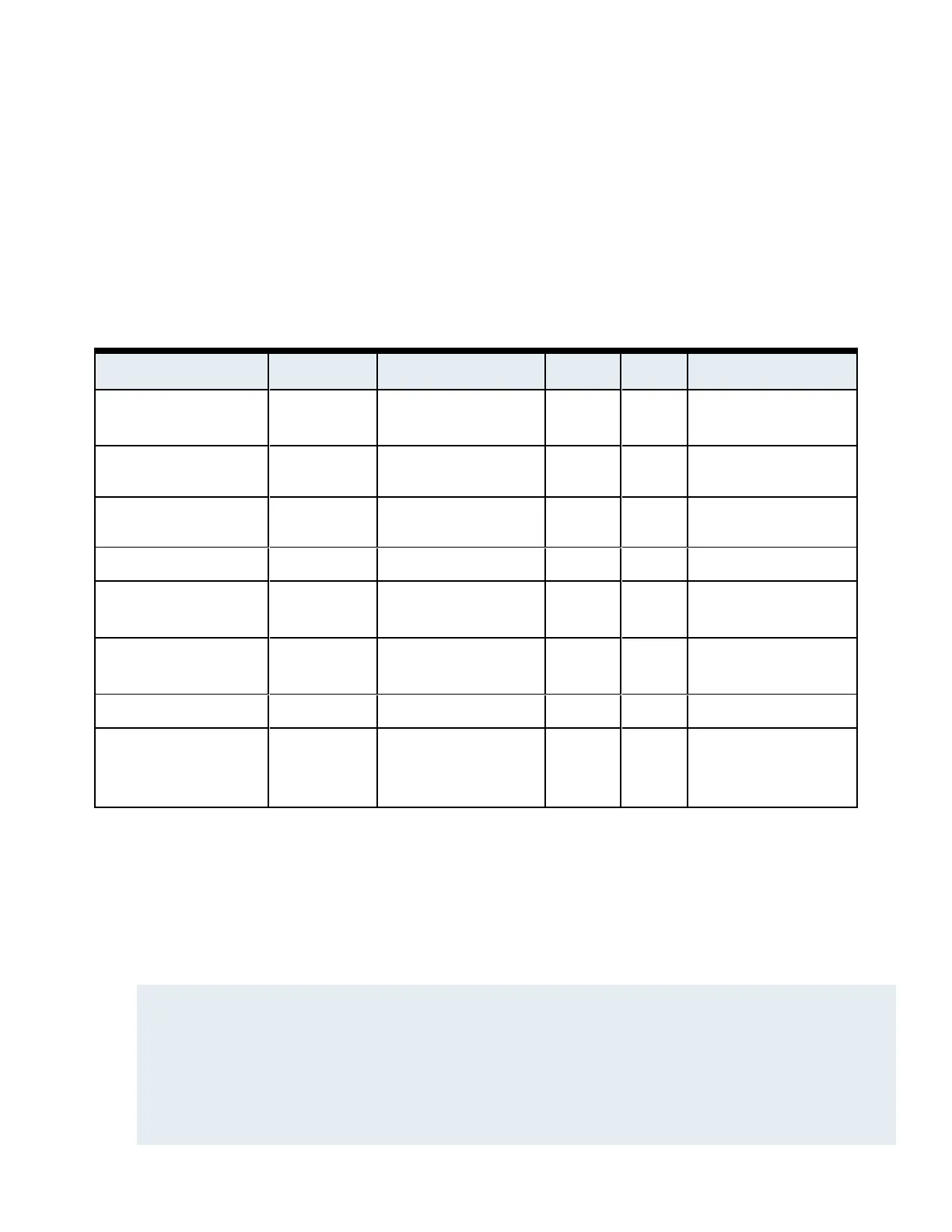
Wiring Specifications and Components
Signal From To AWG Shield Max Length
RS-485 Comm, Data
two wire
iSTAR Ultra G2 RM and I/O Modules 22 Yes 4000 ft (1212m)
Power iSTAR Ultra G2 RM and I/O Modules 22/18 No Range of 600 ft to 1500 ft,
depending on AWG used.
RJ-45-Ethernet iSTAR Ultra G2 Hub, Host Cat 5e or
better
N/A 328 ft (100m)
Supervised Input iSTAR Ultra G2 Input 22/18 No 2000 ft (606m)
Request-to-exit
(REX or RTE)
iSTAR Ultra G2 Switch 22/18 No 2000 ft (606m)
Door Contact /
Door State Monitor(DSM)
iSTAR Ultra G2 Contact 22/18 No 2000 ft (606m)
Supervised Input iSTAR Ultra G2 Input 22 Yes 2000 ft (606m)
Reader Input iSTAR Ultra G2 Proximity/Wiegand
signaling read head
22
20
18
Yes 200 ft (60.96m)
300 ft (91.4m)
500 ft (152.4m)
Table 2:iSTAR Ultra G2 and Components Wiring Specifications
■ There are 2 jumpers on the PoE module:
• x1 jumper to select PoE or PoE Plus (+). Ensure the jumpers are set correctly.
• x1 jumper to configure the voltage used to power the Ultra G2. Set the jumper to 24 VDC for the Ultra G2.
■ Do not connect the PoE injector to a receptacle controlled by a switch.
■ The Tamper, Battery Low, and AC Power Fail inputs must be enabled and connected to report to comply with UL
requirements.
NOTE
AC fail, low battery, and USB cabling must be shielded.
Supervised Inputs must use shielded, 22 AWG (minimum) stranded, twisted-pair cable, such as Belden 9462 or equivalent, for monitor
points, DSMs, and REXs.
Wiring methods must be in accordance with the National Electrical Code, ANSI/NFPA 70.
Connections between PSE or power injector and the PD must use 26 AWG (0.13mm2) for patch cords and 24 AWG (0.21mm2) for
horizontal or riser cables connected through standard 8-pin RJ-45 connectors.
The USTAR-GCM AC Fail and COMM, USTAR-GCM, and USTAR-ACM Tamper, USTAR-GCM power, USTAR-ACM power
(Reader), USTAR-ACM lock 1 and lock 2 connections must remain within 25 feet (7.6 metres) of the control unit.

 Loading...
