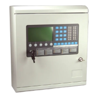
MZX 125/250 Fire Detection Systems
10 Doc. version 1
3 OPERATING INSTRUCTIONS
3.1 OPERATOR’S INDICATORS
AND CONTROLS
3.1.1 GENERAL
ALL operator controls and indicators are mounted on the front panel.
3.1.2 DISPLAY CONTROL MODULE
The Display Control Module (Fig. 3 MZX125 and Fig. 4 MZX250) contain
the following indicators and controls:
A 640 character backlit LCD alphanumeric display, arranged in 16
rows of 40 characters. This is used to display information about the
system status and alarms. The backlight is on when the keyswitch
is set to the ‘enable’ position, when a key is pressed or when an
Alarm or Fault is present.
Switches F1 to F5 - used to carry out the functions displayed on the
bottom line of the LCD display.
An alphanumeric keypad used for entering access codes, text
strings or general information as follows:

 Loading...