EQUIPMENT: T1200-C
PUBLICATION: MARINEC-P-A
ISSUE No. & DATE: 3 02/14
© 2014 Thorn Security Ltd PAGE 25 of 67
Registered Company: Thorn Security Ltd. Registered Office: Dunhams Lane Letchworth Garden City Hertfordshire SG6 1BE
Connection to the panel motherboard is via a 10-way ribbon cable. This carries the power supply connections
and the RS485 serial data comms. The panel must have a C1630 Output Expansion Interface Board fitted and
set for VDR comms (fitted as standard to T1216-C & T1232-C).
DIL switches PN-1 to PN-8 allow the panel number to be set from 1 to 15. The panel number is included in the
messages sent to the ship’s Voyage Data Recorder and therefore aids in identifying the panel. If the panel
number is set to zero then the serial output to the VDR is disabled. DIL switches SP1 & SP2 are for future
requirements and are not used.
Five volt-free relay outputs are provided; two operate on zone fire conditions, the other three are fault relays and
are normally energised (fail-safe operation). The terminals are marked for the normal state of each relay output.
Serial communication with the VDR is provided by the terminals marked Tx+ & Tx- (transmit positive & negative
lines, often also referred to as A & B respectively). This is a RS422 port conforming to IEC 61162-1 (see details
below). Isolation is required only at the listener (VDR). The Tx+ & Tx- terminals should be connected to the Rx+
& Rx- terminals at the VDR. Use standard RS422/RS485 2-core twisted-pair data cable. Maximum cable length
should not exceed 1200m. (NOTE: the implementation of Tx+/Tx- & Rx+/Rx- can vary between manufacturers
and therefore it may be necessary to reverse the connection i.e. Tx+ to Rx- & Tx- to Rx+).
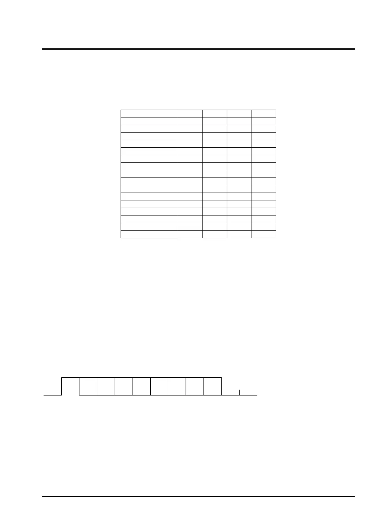
Data is transmitted in serial asynchronous form. The First Bit is a start bit and is followed by 8 data bits, least-
significant-bit first (D0 to D7). The following parameters are used:
Baud rate – 4800
Data bits – 8 (D7=0)
Parity – none
Stop bits – 1
D0 D1
D2 D3
D4 D5
D6 D7
Start
Bit
Stop
Bit
Data Format Protocol:
All transmitted data shall be interpreted as ASCII characters (D7=0).
The valid character set consists of all printable characters (HEX 20 to HEX 7E) except those defined as
reserved characters. Carriage return (0D HEX) & Line Feed (0A HEX) are sent at the end of each sentence.
 Loading...

