T1200
MARINEC-P-A
3 02/14
PAGE 48 of 67
options:
• Fault monitored 28Vdc powered outputs suitable
for operating remote relays complying with the
following requirements:
Field relay requirements: Coil resistance - 2.6k
to 4.5k. Coil Voltage 24Vdc nominal (min 18V,
max 30V), fitted with suppression diode.
(Compatible part: A1466 Relay Board. See
Figure 29).
• Volt-free change over relay version suitable for
switching a maximum of 1 Amp at 30Vdc. DO
NOT USE WITH AC MAINS VOLTAGES.
17.24 Earth Fault monitoring
For installations where earth fault monitoring is
unsuitable, it can be disabled by removal of the
jumper link J18 in the bottom right hand corner of
the C1627 motherboard. This is a non-EN54-2
feature provided for convenience.
18. Panel Repeaters
The T1200-C repeaters duplicate the panel
indications and main user controls at a location
remote from the main panel. The repeater uses the
same motherboard [C1626] as the T1204 fire alarm
panel although most of the components are
depopulated. Up to 5 repeaters can be connected
to a single panel using an RS485 serial connection.
A C1631 repeater interface board needs to be fitted
to connectors J13/J9 located towards the upper
right hand edge of the C1626 motherboard in the
panel and also on each repeater motherboard. If it
is required to activate the Muster condition from a
repeater panel, a C1655 Muster Interface board
needs to be fitted to connector J2 on the
motherboards of the fire panel and each repeater.
[J2 is located middle left hand edge].
Note: The disable/enable/test facilities and the
configuration functions are not available at the
repeaters.
Repeaters are not supplied for use with the
T1204.
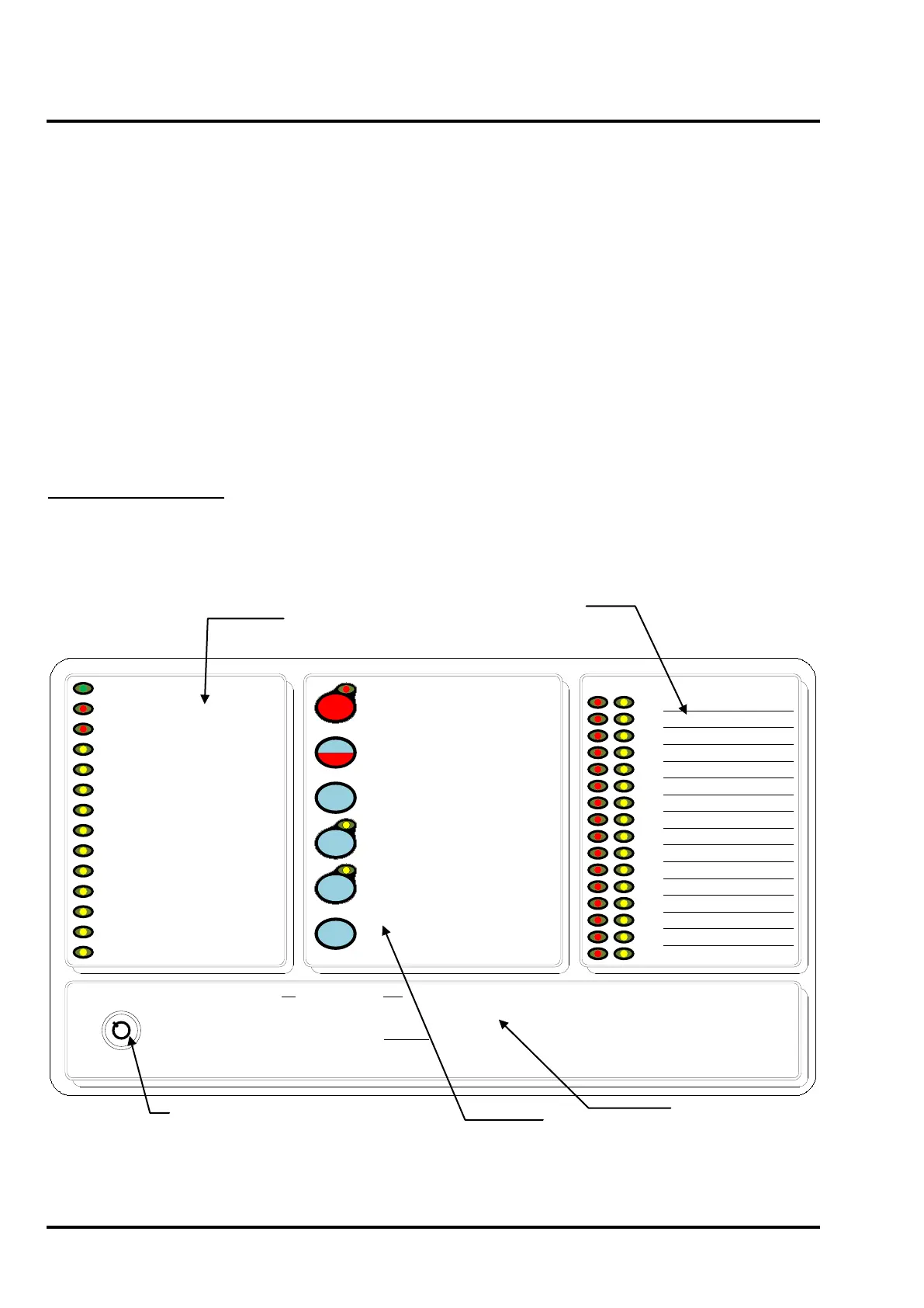
Figure 18 – Repeater Display
1.
2.
3.
4.
5.
6.
7.
8.
9.
10.
11.
12.
13.
14.
15.
16.
0 1
FIRE
POWER SUPPLY ON
POWER SUPPLY FAULT
SYSTEM FAULT
GENERAL FAULT
GENERAL TEST
GENERAL DISABLEMENT
COMMUNICATION FAULT
FAULT OUTPUT FAULT/
DISABLED
SOUNDER FAULT
/DISABLED
SOUNDER TEST
FIRE PROTECTION FAULT/
DISABLED
FIRE OUTPUT ACTIVE
FIRE OUTPUT FAULT/DISABLED
BUZZER
SILENCE
RESET
TEST DISPLAY
ALARMS
RESOUND
SILENCE/
ALARM
MUSTER
FIRE
1. THE RED ZONE INDICATOR
WILL PULSE SHOWING THE
LOCATION OF THE FIRE.
2. CARRY OUT THE
REQUIRED FIRE DRILL.
3. TO SILENCE ALARMS
PRESS SILENCE ALARMS.
4. TO RESET FROM THE FIRE
CONDITION PRESS RESET.
FAULT
1. DETERMINE THE CAUSE OF
THE FAULT.
2. PRESS SILENCE BUZZER.
3. CALL YOUR SERVICE
ENGINEER.
SYSTEM FAULT
THE PANEL IS INOPERATIVE.
ARRANGE FOR ALTERNATIVE
FIRE DETECTION MEASURES.
OVERRIDE
DELAY
Access Controls Keyswitch:
0 – Controls Locked
1 – Controls Unlocked
 Loading...

