T1200
MARINEC-P-A
3 02/14
PAGE 44 of 67
The DELAY LED will not be illuminated unless
the Fire O/P and/or the Fire Protection O/Ps are
optionally configured for the delay mode.
16.8 Overriding the Delay Mode
The panel display includes a Delay Override button
allowing the User to override the delay and operate
the delayed outputs immediately during a fire alarm
condition.
Operation of a Manual Call Point on a zone will also
override the delay.
16.9 Adjustable Display LED
Brightness
On the panel the brightness of the LEDs on the
display can be adjusted to one of 8 levels from full
brightness to dim.
On the repeater the brightness of the LEDs on the
display can be set as either bright or dim.
To change the brightness, set the Access
Keyswitch to the ON position, press the Test
Display button, then within 5 seconds:
• On the panel: press the UP arrow button to
increase the brightness or the DOWN arrow
button to decrease the brightness.
• On the repeater: press the Test Display button
to toggle the brightness (full/dim).
Power-up level is full brightness.
17. Overview of Engineers Functions
This section provides an overview of the functions
available to the engineer.
17.1 Engineer’s configuration process
Most of the Engineer’s configuration facilities are
controlled by DIL switches located on the
motherboard, accessed by opening the panel door.
Each configuration feature has its own dedicated
DIL switch.
Some functions simply require the appropriate DIL
switch to be either ON or OFF.
Where the function is to be applied to selected
zones or outputs, operating the appropriate DIL
switch initiates a programming mode in which the
engineer is able to select the required zone or
output and program the panel to enable or disable
the required function. These programmed operating
modes are stored in EEPROM and are not lost if
the panel is powered down. The relevant DIL
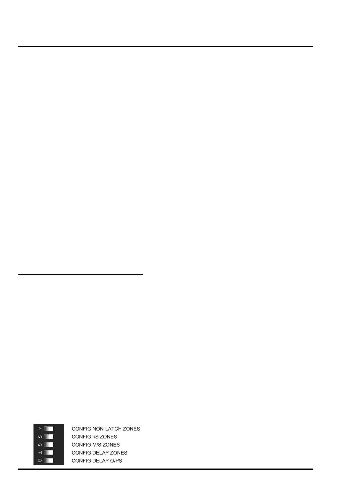
switches are shown below:
17.2 Zone/Output selection
When one of the zone or output configuration DIL
switches is switched to the ON position, the panel
sounds the internal buzzer and illuminates the
SYSTEM FAULT LED to indicate that the
programming mode has been initiated. Any circuits
which already have that mode set will have their
fault LED illuminated.
The engineer can then use the Cursor Select
feature to select the required zone or output by
moving a flashing cursor indication up or down
through the yellow fault LEDs associated with the
available zones and outputs until the required zone
or output is highlighted.
Note that in the Engineer’s programming mode, any
faults, or disablements are masked and are not
shown on the display. The panel will not respond to
faults or fires.
With the cursor flashing on the required
zone/output, pressing the Disable button disables
the required function for that zone/output
(corresponding fault LED is OFF). Pressing the
Enable button enables the required function for that
zone/output (corresponding fault LED is ON).
Once all required zones/outputs have been
programmed and the configuration DIL switch is
returned to the OFF position, the panel will return to
normal operation.
NOTE: DIL switch 7 – CONFIG DELAY ZONES is
not applicable to the T1200-C range of panels.
The factory default configuration for the zones
and delayed outputs can be restored by selecting
all five configuration DIL switches for the zones and
outputs to ON then pressing the Disable switch on
the display and finally setting the configuration
switches back to the OFF position.
Factory default:
All zones are latching fire, not intrinsically safe,
not machinery space.
All outputs operate immediately (not delayed).
The following sections describe the available
configuration options.
17.3 Configure Delayed Outputs
Having operated the DIL switch for configuring
delayed outputs the required output can be
selected via the Cursor Select feature and can be
set as either a Delayed output or a Non-Delayed
output. If the output is set to the delayed mode, the
appropriate output fault LED will be illuminated.
The following outputs can be independently
programmed as delayed or non-delayed:
i) All Sounder Circuits (panel & output boards)
unless in CREW mode
ii) Fire Output
iii) All Fire Protection Outputs (panel & output
 Loading...

