Do you have a question about the Tyco Visonic MC-302EL PG2 and is the answer not in the manual?
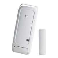
The MC-302EL PG2 is a two-way wireless PowerG magnetic contact device designed for compatibility with PowerMaster control panels (version X and above). This versatile device integrates a built-in reed switch and an auxiliary hard-wired input, offering flexible configuration options. The reed switch detects the opening of a door or window when a magnet placed nearby is removed, while the auxiliary input can be programmed as Normally Open (N.O.), Normally Closed (N.C.), or End-Of-Line (E.O.L.) for use with various external sensors such as pushbuttons, detectors, or additional door contacts. The device can be configured via the PowerMaster control panel to disable the magnet-operated reed switch if only the auxiliary input is required. Both the reed switch and auxiliary input function as separate transmitters, though they trigger the same RF transmitter, sending specific alarm parameters to the control panel using PowerG two-way communication protocol.
The MC-302EL PG2 features a tamper switch that activates when the cover is removed, ensuring system integrity. A periodic supervision message is automatically transmitted to the control panel, informing it of the unit's active participation in the system at regular intervals. An LED indicator lights up whenever alarm or tamper events are reported, but not during the transmission of supervision messages. The device is powered by an on-board 3V Lithium CR-123 type battery (Panasonic, Sanyo, or GP only), with an expected battery life of 8 years under typical use. A "low battery" message is sent to the receiver when the battery voltage is low, and automatic transmission of battery condition data occurs as part of periodic status reports and immediately upon low battery condition detection.
For installation, it is recommended to attach the transmitter to the top of the door/window's fixed frame and the magnet to the movable part, ensuring the magnet is located no more than 6 mm (0.25 in.) from the transmitter's marked side. A back tamper switch (optional) is located under the PCB; it is crucial to fasten the break-away base segment to the wall. If the detector unit is forcibly removed, this segment breaks away, causing the tamper switch to open. When removing the cover, a tamper message is transmitted. To prevent the receiver from remaining in permanent alert (due to "TAMPER RESTORE" not being transmitted), the tamper switch should be pressed while removing the battery.
The auxiliary input wiring supports N.C. sensor contacts (series connected) or N.O. sensor contacts (parallel connected). For E.O.L. supervision, N.C. sensor contacts can be used with a 47KΩ E.O.L. resistor wired at the far end of the zone loop. For UL installations, the device connected to the initiating circuit must be in the same room as the transmitter. The device transmits an alarm message if the loop is opened or short-circuited.
Enrollment involves accessing the PowerMaster panel's Installer Menu, selecting "02:ZONES/DEVICES," and then choosing "ADD NEW DEVICE" or "MODIFY DEVICES" if already enrolled. The process includes enrolling the device or entering its ID, selecting the desired Zone Number, and configuring Location, Zone Type, Chime Parameters, and the Magnet. Device parameters can be configured via the "DEVICE SETTINGS" option, allowing the installer to determine whether the alarm LED indication is ON (default) or OFF, enable (default) or disable the internal reed switch, and define the external input as Disabled (default), EOL-End Of Line, Normally Open, or Normally Closed.
A local diagnostics test can be performed to check signal strength. After separating the base from the cover, press and release the tamper switch. Re-attach the cover, then momentarily open the door or window to verify the red LED blinks, indicating detection. After 2 seconds, the LED blinks 3 times. The LED response (Green for Strong, Orange for Good, Red for Poor, No blinks for No communication) indicates received signal strength. A "poor" signal strength is unacceptable, requiring relocation and re-testing until a "good" or "strong" signal is received.
The MC-302EL PG2 operates in frequency bands of 433-434 MHz and 868-869 MHz for Europe and the rest of the world, and 912-919 MHz for the USA. It has an operating temperature range of 0°C to 49°C (32°F to 120°F) and an average relative humidity of approximately 75% non-condensing (up to 85-95% for 30 days per year). The device dimensions are 81 x 34 x 25 mm (3-3/16 x 1-1/4 x 1 in.) and it weighs 53g (1.9 oz) including the battery. It complies with various standards including EN 301 489-3, EN 50130-4, EN 300 220-2, EN 60950-1, EN 50130-5, EN 50131-1, EN 50131-6, EN 50131-2-6: 2008, and is compatible with RTTE requirements (Directive 1999/5/EC). It is suitable for systems conforming to PD6662:2010 at Grade 2 and environmental class 2 in the UK. It also complies with FCC Part 15 and Industry Canada license-exempt RSS standards. The device's two-way communication functionality, while providing additional benefits, has not been tested to comply with respective technical requirements and is considered outside the scope of the product's certification.
The device's performance regarding opening and closing distances varies depending on the mounting surface:
The manufacturer warns that changes or modifications not expressly approved by Visonic Ltd. could void the user's FCC or other authority to operate the equipment. To comply with FCC and IC RF exposure requirements, the device should be located at least 20 cm from all persons during normal operation. The antennas used for this product must not be co-located or operated with any other antenna or transmitter. Regular testing of wireless devices is recommended to ensure proper functioning and protection against faults.
| Brand | Tyco |
|---|---|
| Model | Visonic MC-302EL PG2 |
| Category | Security System |
| Language | English |