EasyManua.ls Logo

Tyco Power Series User Manual

Tyco Power Series
36 pages
To Next Page IconTo Next Page
Page #1 background imageLoading...
Page #1 background image
Quick Setup
1
Plan
Plan the installation including all alarm detection devices, zone
expanders, keypads and other required modules.
2
Mount Decide on a location for the alarm panel and secure it to the
wall using suitable mounting hardware.
3
Wire Complete all wiring including modules, zones, bells/sirens,
telephone line connections and ground connections. Record
module serial numbers on page 24.
4
Power Connect the battery and power up the system. The battery must
be connected.
5
Enroll First
Keypad
Hardwired: Wire the keypad to the Corbus, power up the alarm
panel then press any button on the keypad. Wireless: Wire the
HSM2Host to the Corbus, then power up the alarm panel and a
wireless keypad. Press any button on the keypad to enroll it. The
HSM2Host is then enrolled on the alarm panel. Alternately,
enroll an RF keypad.
6
Enroll
modules
[*][8][Installer Code][902] subsection [000]. Press [*] to begin
auto-enrollment. Module slots are automatically assigned. Use
scroll keys to view slots. Change slot by typing a 2-digit number.
7
Enroll
wireless
devices
[*][8][Installer Code][804] subsection [000]. Note: An
HSM2HOST or RF keypad must be enrolled first.
8
Program Basic programming: [*][8][installer code] [001]/[002]> Zone
Type/Zone Attribute [005]>[001] Partition 1 Timers: Entry
Delay 1 Entry Delay 2 Exit Delay [301]>[001] Phone #1
[310]>[000] System Account Code.
9
Test Test the panel completely to ensure that all features and
functions operate as programmed. [901] Walk Test [904]
[000] Wireless Placement Test.
Compatible Devices
Throughout this document, x in the model number represents the operating
frequency of the device as follows: 9 (912-919 MHz), 8 (868 MHz), 4
(433 MHz).
Note: Only models operating in the band 912-919 MHz are UL/ULC
listed where indicated. For UL/ULC certified installations, use only
UL/ULC listed devices. Only models marked with xxx
UL
are UL/ULC
listed.
Table 1-1 Compatible Devices
Modules
Wireless keypads: HS2LCDWFPROx
UL
HS2LCDWFVPROx
UL
Hardwired keypads with PG host HS2LCDRFPROx
UL
Hardwired keypads: HS2LCDPRO
UL
Touchscreen keypad: HS2TCHPRO(BLK)
UL
Note: For ULC-s559 Listed applications the HS2TCHPRO(BLK) touchscreen keypad is for supplementary
use only.
2-way wireless transceiver: HSM2HOSTx
UL
8-zone expander: HSM2108
UL
8 low current output expander: HSM2208
UL
8-zone expander: HSM3408
UL
1 A Power supply: HSM2300
UL
3 A power supply: HSM3350
UL
4 high current output expander: HSM2204
UL
Audio verification module: HSM2955(R)
UL
Power supply/relay output/Corbus repeater
module:
HSM3204CX
UL
USB to WiFi adapter: HSM3WIFI
Alternate communicator: LE9080
UL
3G9080-EU
3G9080
UL
3H9080
UL
GS9080
TL880LT
UL
TL8803G
UL
Hardwired Devices
2-wire smoke detectors: FSA-210x
UL
FSA-210xT
UL
FSA-210xS
UL
FSA-210xST
UL
FSA-210xLST
UL
FSA-210xR
UL
FSA-210xRT
UL
FSA-210xRS
UL
FSA-210xRST
UL
FSA-210xLRST
UL
y= A, B, or C
A: ULC listed models
B: UL listed models
C: European and Australian models
4-wire smoke detectors: FSA-410x
UL
FSA-410xT
UL
FSA-410xS
UL
FSA-410xST
UL
FSA-410xLST
UL
FSA-410xR
UL
FSA-410xRT
UL
FSA-410xRS
UL
FSA-410xRST
UL
FSA-410xLRST
UL
y= A, B, or C
A: ULC listed models
B: UL listed models
C: European and Australian models
CO detectors: CO-12/24
UL
12-24SIR
UL
FW-CO12
FW-CO1224
CO1224
Wireless Devices
PowerG wireless short range ceiling mount detector with temperature
monitoring
PGx862
UL
PowerG wireless long range ceiling mount detector with temperature
monitoring
PGx872
UL
PowerG wireless outdoor curtain PIR PGx902
UL
PowerG wireless PRI motion detector with optional animal resistance PGx904(P)
UL
PowerG wireless PIRmotion detector with temperature monitoring PGx914(P)
UL
PowerG wireless curtain PIR motion detector PGx924
UL
PowerG wireless PIR motion detector with camera PGx934(P)
UL
PowerG wireless outdorr PIRmotion detector with camera and with anti-
masking
PGx944
UL
PowerG wireless mirror optic PIR motion detector PGx974(P)
UL
PowerG wireless dual technology (PIR and MW) with anti-masking PGx984(P)
UL
PowerG wireless outdoor PIRmotion detector with anti-masking PGx994
PowerG wireless recessed door/window contact PGx307
PowerG wireless outdoor contact with auxiliary input, temperature
monitoring, and anti-masking
PGx312
UL
PowerG wireless door/window contact with auxiliary input PGx945
UL
PowerG wireless vanishing door/window contact PGx975
UL
/ PGx303
UL
PowerG wireless glassbreak detector PGx912 / PGx922
UL
PowerG wireless shock detector with auxiliary input PGx935
UL
PowerG wireless flood detector PGx985
UL
PowerG wireless temperature detector PGx905
UL
PowerG wireless temperature probe extender (requires PGx905) PGTEMP-PROBE
PowerG wireless CO detector (USonly) PGx913
UL
PowerG wireless CO detector with temperature monitoring PGx933
UL
PowerG wireless smoke and heat detector PGx916
UL
PowerG wireless smoke and heat detector with temperature monitoring PGx936
UL
PowerG wireless smoke detector PGx926
UL
PowerG wireless indoor siren PGx901
UL
PowerG wireless outdoor siren PGx911
UL
PowerG wireless repeater PGx920
UL
PowerG wireless 1-button securtiy panic keyfob PGx938
UL
PowerG wireless 2-button securtiy panic keyfob PGx949
UL
WARNING: This manual contains information on limitations regarding product use and function and information on the
limitations as to liability of the manufacturer. The entire manual should be carefully read.
To download the full installation and user manuals and register your product, please visit:
www.DSC.com/m/29010134 or scan the QR code to the right.
PowerSeries Pro Alarm Control Installation Guide
PowerSeries Pro is a feature-rich, scalable alarm system designed for commercial use. It features integrated phone line and Ethernet (IP) communicators,
and supports both hardwired and wireless devices. Three models are available: HS3248 (248 zones), HS3128 (128 zones), and HS3032 (32 zones).
Question and Answer IconNeed help?

Do you have a question about the Tyco Power Series and is the answer not in the manual?

Tyco Power Series Specifications

General IconGeneral
SeriesPower Series
CategorySecurity System
System TypeWired/Wireless Hybrid
Power SupplyAC with battery backup
CommunicationIP
Remote AccessMobile app, web portal
Alarm Typefire, medical

Summary

Quick Setup

Initial Planning and Wiring

Covers initial planning, device selection, panel mounting, and system wiring procedures.

System Enrollment

Details steps for enrolling keypads, modules, and wireless devices using installer programming.

System Programming and Testing

Guides on configuring system settings, delays, and performing functional tests.

Compatible Devices

Hardwired and Wireless Device Lists

Lists compatible hardwired and wireless devices, including detectors, keypads, and modules.

Safety Instructions

Before Installing Equipment

Ensures package contents are verified, manuals are read, and all instructions are followed before installation.

Selecting Suitable Location

Guidance on choosing an optimal installation site, considering power, phone access, and environmental factors.

Safety Precautions During Installation

Highlights critical safety measures like avoiding lightning, proper wiring, and using correct power supplies.

Installation

Compatible Enclosures

Details compatible enclosures for the main board, including materials, dimensions, and weight specifications.

Wall Mounting HSC3010C/CR/CAR

Provides diagrams and steps for mounting the HSC3010C, HSC3010CR, and HSC3030CAR enclosures.

Wall Mounting HSC3020C

Provides diagrams and steps for mounting the HSC3020C enclosure, including component placement.

Wall Mounting HSC3020CP

Provides diagrams and steps for mounting the HSC3020CP enclosure, noting UL/ULC compliance.

Installing HSM3204CX Module

Details wiring and routing for the HSM3204CX module within an HSC3010C enclosure.

Terminal Descriptions

Installing HSM3350 Module

Details wiring and routing for the HSM3350 module within an HSC3010C enclosure.

PowerSeries Pro Terminal Functions

Explains the purpose and function of each terminal on the PowerSeries Pro alarm controller.

System Design and Power Considerations

Corbus Wiring Guidelines

Covers wire types, length limits, connection methods, and limitations for Corbus modules.

Current Ratings

Details system output ratings, current draw limits for components, and power budget considerations.

Capacitance Limits

Explains how capacitance affects Corbus wire length and provides relevant tables.

Power Supply Specifications

AC Power Supply Details

Covers UL/ULC and International AC power supply requirements, energy efficiency, and warnings.

Battery Requirements

Specifies battery types, standby time, recharging, and connection procedures for system backup.

Additional Wiring

Zone Wiring Procedures

Guides on wiring zones, including EOL/SEOL/DEOL configurations, resistance, and wire gauge.

Aux Power Wiring

Explains the use of AUX terminals for powering devices, their current limits, and protection.

PGM Wiring

Details PGM output terminals, current limits, relay requirements, and specific PGM functions.

Bell Wiring

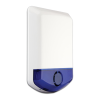
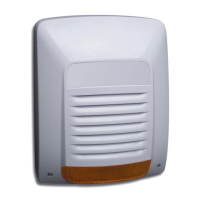
Describes bell output specifications, current limits, polarity, and supervision for alarm sounding devices.

Telephone Line Wiring

Provides instructions for connecting the telephone line to the system using RJ-31X connectors.

System Setup and Configuration

Earth Ground Wiring

Instructions for connecting the earth ground for safety, proper operation, and compliance.

Enrollment Procedures

Outlines steps for enrolling modules and wireless devices onto the system via installer programming.

Programming Methods

Lists methods for programming the system, including DLS software and direct keypad access.

Viewing Programming

Explains how to access and view system programming sections from any keypad.

Initial System Configuration

Covers essential programming steps like time/date setup and minimum required settings post-installation.

Language Selection

Guide to selecting the preferred language for the system interface and keypad display.

Partition Setup

Procedures for setting up partitions, bell operation, and assigning keypads to partitions.

Assign Zone Types

Defines the operational role of each zone within the system when triggered.

Assign Zone Attributes

Configures specific zone behaviors like bypass, swinger shutdown, EOL settings, and other attributes.

Troubleshooting

LCD Keypad Trouble Display

How to use the keypad to view and interpret trouble conditions indicated on the LCD screen.

[*][2] Trouble Display Feature

Accessing and navigating the system's trouble menu via keypad for detailed fault information.

Trouble Indications Overview

A categorized list of trouble codes and their meanings to aid in diagnosing system faults.

Troubleshooting

Power and Bus Voltage Troubles

Diagnoses faults related to bus voltage issues for modules, keypads, and power supplies.

Device Faults and Battery Issues

Addresses common device faults, tamper conditions, low battery alerts, and RF communication loss.

Communication and Module Faults

Covers communication path failures, module supervision loss, and tamper conditions on modules.

Troubleshooting

Network and AUX Output Troubles

Diagnoses issues with wireless devices not networked and AUX output voltage problems.

Limit Exceeded Troubles

Identifies configuration errors where panel limits for zones or partitions are exceeded.

Specifications

Zone Configuration and Access Codes

Details supported zone types, attributes, expansion methods, and access code management.

Power Supply and Output Ratings

Covers power supply specs, memory, current draw, and ratings for Bell/Aux+ outputs.

Operating Environmental Conditions

Specifies the acceptable temperature and humidity ranges for reliable system operation.

Alarm Transmitter Equipment (ATE) Specs

Details the specifications for the integrated alarm transmitter equipment (ATE) and its capabilities.

Additional System Features

Lists advanced system features such as 2-way audio, visual verification, and PGM scheduling.

Programming Directory

Labeling and Zone Configuration

Sections for programming zone labels, partition names, system labels, and defining zone types.

EOL, Time, and PGM Settings

Covers configuration for EOL resistors, system time delays, PGM outputs, and related parameters.

Access Code Management

Sections for defining and managing installer, master, maintenance, and guard access codes.

Programming Directory

System Options Configuration

Extensive settings for customizing system behavior, including various 'System Options' categories.

Programming Directory

Module and Wireless Device Records

Tables for logging installed modules and wireless devices, including type, slot, zone, and serial number.

Communications

Account Code and Format Settings

Configuration for system account codes and defining communicator formats for SIA and Contact ID reporting.

Communication Variables

Parameters for communication delays, attempts, test transmissions, and network settings.

System Configuration and Programming

DLS, Schedule, and Audio Options

Settings for DLS software connection, time-based schedules, and 2-way audio features.

Wireless, Cellular, and Communicator Settings

Configuration for wireless devices, cellular modules, RF jam detection, and communicator parameters.

System Configuration and Programming

Keypad Programming Options

Customizing keypad functions, display behavior, LED indicators, and security options.

Warranty, Disclaimer, and System Failures

Limited Warranty Details

Explains the warranty period, coverage terms, and procedures for obtaining service or repair under warranty.

Disclaimer of Warranties

States warranty limitations, exclusions of implied warranties, and governing laws for DSC products.

Out of Warranty Repairs

Information on the procedures, charges, and replacement options for products requiring repair outside the warranty period.

System Failures and Recommendations

Discusses potential system failures, the importance of installer communication, and troubleshooting advice.

Installer Defined Codes

Installer Code Configuration

Setting the primary installer access code for system programming and access to installer menus.

Master Code Configuration

Defining the master access code for system operation, user management, and general access.

Maintenance Code Configuration

Establishing a maintenance access code for specific system tasks or diagnostics.

System Account Code Setup

Configuring the system account code, typically used for reporting to a central monitoring station.

Detector Placement and Escape Planning

Smoke Detector Placement Guide

Recommendations for installing smoke detectors in residential environments for optimal fire safety.

Carbon Monoxide Detector Placement

Guidelines for locating CO detectors to ensure effective detection of carbon monoxide hazards.

Fire Escape Planning Essentials

Advice on developing and rehearsing family escape plans to ensure rapid and safe evacuation during a fire.

Regulatory Approvals

FCC Compliance Statement

Information regarding compliance with FCC rules for digital devices, radio frequency energy, and interference.

Important Information and USOC Jack

Key details including FCC registration, RJ-31X jack requirements, and telephone connection guidelines.

Innovation, Canada (ISED) Statement

Compliance statement for Canadian ISED regulations, including Ringer Equivalence Number (REN).

UL/ULC Installation Standards

Lists the UL/ULC standards the product complies with for various alarm applications and installation types.

UL/ULC Compliance and Installation Requirements

Local, Central Station, Police Connect

Specific installation requirements for UL/ULC standards related to local, central station, and police connect systems.

ULC Commercial Burglary Security Levels

Installation guidelines and requirements for ULC commercial burglary applications according to security levels.

UL Home Health Care Signaling

Specific requirements for installing UL Home Health Care Signaling Equipment and system configurations.

ULC Central Station Fire/Burglary Monitoring

Installation requirements for ULC central station fire and burglary monitoring systems.

SIA False Alarm Reduction

Quick reference for programming sections and features required for SIA False Alarm Reduction compliance.

System Protection and User Guidance

Bell Location Requirements

Guidance on where to locate the alarm sounding device (bell) for maximum audibility and system effectiveness.

Control Unit Protection

Methods for protecting the control unit and power supply within a secure, armed area of the premises.

Guidance for Casual Users

Advice for installers on cautioning users about sharing system information and providing secure access.

User Information for Manual

Key information installers should advise users to note in the User's Manual for system operation.

Battery and Compliance Information

Aux Loading and Battery Selection

Table detailing battery requirements based on enclosure, standby time, loading, and recharging parameters.

European EN50131 Compliance Statement

Details compliance with EN50131 standards, including applicable functions, zone types, and system configurations.

SIA False Alarm Reduction and Installation Notes

SIA False Alarm Reduction Quick Reference

Programming sections and features relevant to SIA False Alarm Reduction compliance, including delay settings.

Installation Notes and Warnings

Important notes regarding fire alarm verification, call waiting, system testing, and specific installation warnings.

SIA Programming Quick Reference

Exit Time and Delay Settings

Programming sections for exit delays, entry delays, abort windows, and related timing configurations.

Abort, Duress, and Cancel Window Settings

Configuration for aborting alarms, duress codes, cancelling communication windows, and reporting codes.

Cross Zoning and Swinger Shutdown

Settings for cross zoning functionality and swinger shutdown parameters for zone alarms.

Warranty, Disclaimer, and System Failures

Limited Warranty Details

Explains the warranty period, coverage terms, and procedures for obtaining service or repair under warranty.

Disclaimer of Warranties

States warranty limitations, exclusions of implied warranties, and governing laws for DSC products.

Out of Warranty Repairs

Information on the procedures, charges, and replacement options for products requiring repair outside the warranty period.

System Failures and Recommendations

Discusses potential system failures, the importance of installer communication, and troubleshooting advice.

System Failures and Potential Issues

Installation and Criminal Impact

Risks from inadequate installation, criminal techniques, and system vulnerabilities affecting protection.

Power, Battery, and RF Issues

Problems related to power interruptions, battery failure, RF signal compromise, and interference.

Device and User Limitations

Challenges with system user operation, smoke/motion detector limitations, and warning device effectiveness.

External System Factors

Impact of telephone line issues, component failure, insufficient time for response, and environmental factors.

System Testing and Security Considerations

Inadequate Testing Impact

How lack of regular testing and maintenance can lead to system problems and prevent intended operation.

Security and Insurance Limitations

Clarifies that an alarm system is not a substitute for property or life insurance coverage.

Related product manuals