PowerSeries Pro Installation Guide
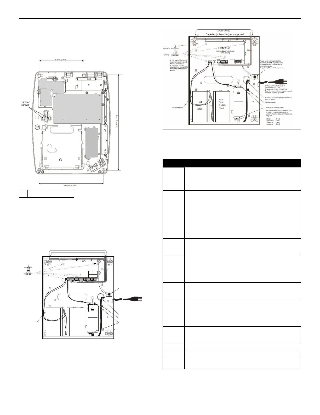
Wall mounting the HSC3020CP enclosure
The following diagram indicates the mounting location of the alarm
controller PCB, wireless receiver, power supply module and tamper
bracket inside the HSC3020CP enclosure.
Figure 1-3 HSC3020CP enclosure
A Tamper screws
Note: The HSC3020CP is used only for EN50131 and NFA2P certified
installations.
Installing the HSM3204CX in HSC3010C enclosure
The following diagram indicates the routing of power limited and non-
power limited wiring inside the enclosure. Battery leads and AC cord are
non-power limited. All other wiring is power limited.
Figure 1-4 HSM3204CX in HSC3010C enclosure
STAND OFF
PC BOARD
CABINET
POWER LIMITED
Cable ties (not supplied) recommended
1. Insert standoff into cabinet
mounting hole in the desired
location. Snap in place.
2. Position circuit board mounting
holes over standoffs. Press firmly
on board to snap in place.
Primary: 120VAC, 60Hz, Class VI
Secondary: 18V DC, 3.6A
Power adapter module: HS65WPSNA
Note: Do not connect Power adapter
module to receptacle controlled by a switch
4Ah
7Ah
2 x 7Ah
17Ah
Red -
Black +
Plastic grommet strip (Not supplied) recommmended
Power supply mounting screws
Cable tie required
Tamper switch and mounting bracket
Note: Power supply may be mounted outside the
cabinet. Use the following guide to determine
sutiable distance and guage:
DISTANCE GAUGE
2 meters/6.5ft 22AWG
3 meters/10ft 20AWG
4 meters/13ft 18AWG
Cable tie required
Wire tamper switch to any Corbus zone.
Program zone as 24-Hour Latching or Non-Latching tamper.
Supports NC, EOL or DEOL supervision.
HSM3204CX
Warning: Disconnect AC power
before servicing.
Installing the HSM3350 in the HSC3010C enclosure
The following diagram indicates the routing of power limited and non-
power limited wiring inside the enclosure. Battery leads and AC cord are
non-power limited. All other wiring is power limited.
Figure 1-5 HSM3350 in HSC3010C enclosure
Terminal descriptions
The following terminals are available on the PowerSeries Pro alarm
controller.
Table 1-2 Terminal descriptions
Terminal Description
BAT+,
BAT-
Battery terminals. Use to provide backup power during a power outage
and additional current when system demands exceed the power output of
power adapter, short term such as when the system is in alarm.
Do not connect the battery until all other wiring is complete.
DC +, DC - The HS65WPS power adapter supplies 18 VDC power input to the alarm
controller.
Note: For CE/EN certified applications, the name of the power , the name
of the power adapter is HS65WPS. For UL/ULC listed applications, the
name of the power adapter is HS65WPSNA. For ULC Commercial Fire
Listed applications and ULC Commercial Burg Security Level 4
applications, the name of the power adapter is HS65WPSNAS.
Connect the battery before connecting the AC. Do not connect the battery
or power adapter until all other wiring is complete.
AUX+,
AUX-
Auxiliary terminals. Use to power detectors, relays, LEDs, etc. (2 A max).
Connect the positive side of device to one of the three AUX+ terminals
and the negative side to AUX- or COM.
BELL+,
BELL-
Bell/Siren power (700 mA continous, 2A max short term). Connect the
positive side of any alarm warning device to BELL+, the negative side to
BELL-.
Note: For EN50131 and UL/ULC listed applications, use maximum 700
mA load on the BELL output.
RED, BLK,
YEL, GRN
Corbus terminals. Use to provide power and communication between the
alarm controller and connected modules. Each module has four Corbus
terminals that must be connected to the Corbus.
PGM1 to
PGM4
Programmable output terminals. Use to activate devices such as LEDs,
relays, buzzers, etc.
(PGM1, PGM4: 100 mA; PGM2: 300 mA or can be configured for use as
a 2-wire smoke detector interface, max loop current 100 mA;
PGM3: 300 mA (negative trigger) or 1 A (positive trigger)
Z1 to Z8
COM
Zone input terminals. Ideally, each zone should have one detection
device; however, multiple detection devices can be wired to the same
zone.
EGND Earth ground connection
ETHERNET Ethernet port
TIP, RING,
T-1, R-1
Telephone line terminals
*x= none use for CE/EN certified applications
x= NA use for UL/ULC listed applications
- 4 -
 Loading...