TYCROP Manufacturing Ltd. QuickPass Top Dresser Setup Manual
Setup Instructions Page 3
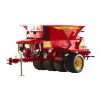
Figure 7: Decal Placement
3. Remove the battery and the battery box from the crate.
4. Remove the two middle black plugs on the top of the
QuickPass hitch tube (Figure 8).
Figure 8: Remove battery plugs
5. Line up the battery box and battery with the holes and
attach with the battery clamp and two 7.8 x 175 mm
(5/16 x 7 in) bolts. Ensure that the battery posts are
towards the front of the machine.
6. Remove the Honda engine from the crate and mount
the engine assembly to the hitch tube straddling the
four tabs welded to the hitch assembly.
NOTE – Ensure that the engine’s fuel tank is facing out
towards the front of the machine.
7. Install the four 9.4 x 25 mm (⅜ x 1 in) tank mounting
bolts. Install the rear ones first and then the front. Use
the supplied washers and nylon locking nuts. Position
the tank to ensure that the hood does not come in contact
with the front hopper wall when opening and closing.
8. Install the hood bumper bracket to the hitch assembly.
Then line it up so when the hood assembly is in the open
position, the hood will rest in the center of the round
bumper. Tighten the bolt holding the bracket to the hitch
assembly.
NOTE – All the hydraulic hoses are numbered for easier
installation. Loosely connect all the hoses to their proper
connections before tightening. See Figure 16 for hose
description and placement.
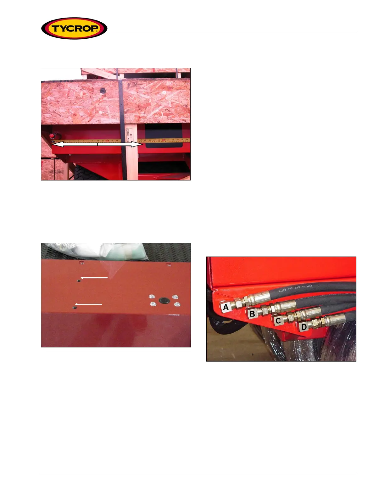
9. Connect the #5 hose to the ‘B’ fitting on the side of
the QuickPass (Figures 9 and 13).
10. Connect the #3 hose to the ‘C’ fitting on the side of
the QuickPass (Figures 9 and 13).
11. Connect the #2 hose to the ‘D’ fitting on the side of
the QuickPass (Figures 9 and 13).
Figure 9: Connect hydraulic hoses to fittings
12. Connect the #4 hose to the ‘IN’ port of the flow
control valve (Figures 10 and 13).
13. Connect the #8 hose to the ‘EX’ port of the flow
control valve (Figures 10 and 13).
20 inches
 Loading...