2008 15 210OPTRS
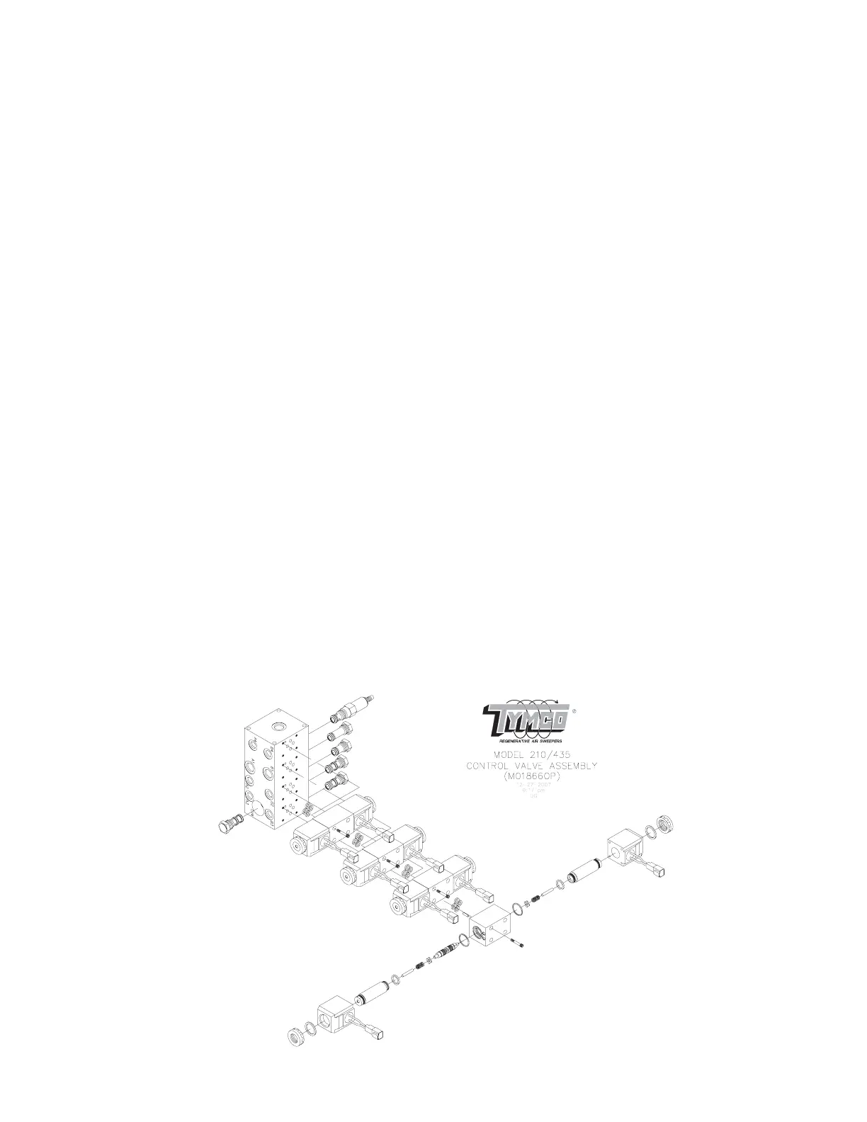
C. CONTROL VALVES
The hydraulic control valve assembly is used to control the flow of oil to the various
hydraulic components. The Model 210 valve assembly is located behind the door on
the left rear hopper hinge panel (See Page 3).
A relief valve is used to set the pressure for the Model 210 hydraulic system which is
1500 PSI (103.5 Bar) for the standard left-hand gutter broom option. For Dual Gutter
Broom Option: 2500 PSI (172.5 Bar) for the primary pressure for the gutter brooms
and 1500 PSI (103.5 Bar) for secondary pressure. Once set, no further adjustment is
necessary; however, at least once a year, or if components appear sluggish, have
pressure setting tested. (Refer to Parts & Service Manual for procedure.)
The control valves are solenoid actuated, meaning that they are shifted by use of
electric toggle switches. These toggle switches are located on the control console
panel inside the cab - except the dump switch which is located externally. Should
toggle switch control fail to activate component, manual override buttons are pro-
vided at each valve to manually engage component. Before manually shifting valves,
make sure the wires are plugged into the valve solenoids. Should the switch fail to
activate the component, manual override buttons are provided on the top and bottom
of each valve segment. Use the following procedure to engage the manual override
buttons:
1. Locate valve segment not functioning.
2. Set auxiliary engine RPM at idle.
3. Use a screwdriver or similar device to push manual override button into valve
(considerable force must be exerted to overcome springs inside valve).
NOTE: Gutter broom can only be raised when manually shifting valve. If an at-
tempt is made to lower gutter broom manually, bristles may rotate, but
broom will not lower due to lock valve engagement.
If a solenoid shorts out, it will cause the hydraulic system fuse to blow. The fuse is lo-
cated at the control console assembly inside the cab (See Page 4). To replace sole-
noid, refer to the Parts & Service Manual.