LEA-6 / NEO-6 - Hardware Integration Manual
GPS.G6-HW-09007-A Preliminary Design-in
Page 30 of 62
For the correct calculation of the micro strip impedance, one does not only need to consider the distance
between the top and the first inner layer but also the distance between the micro strip and the adjacent GND
plane on the same layer
Use the Coplanar Waveguide model for the calculation of the micro strip.
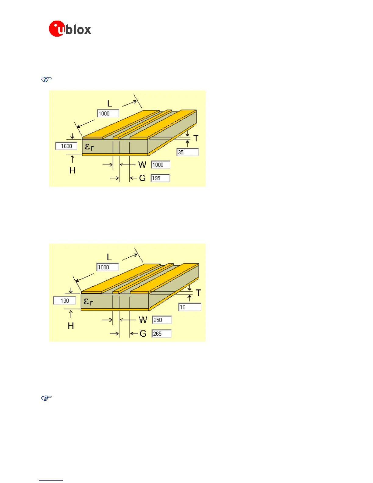
Figure 22: Micro strip on a 2-layer board (Agilent AppCAD Coplanar Waveguide)
Figure 22 shows an example of a 2-layer FR4 board with 1.6 mm thickness and a 35µm (1 ounce) copper
cladding. The thickness of the micro strip is comprised of the cladding (35µm) plus the plated copper (typically
25µm). Figure 23 is an example of a multi layer FR4 board with 18µm (½ ounce) cladding and 180µ dielectric
between layer 1 and 2.
Figure 23: Micro strip on a multi layer board (Agilent AppCAD Coplanar Waveguide)
2.5 Antenna and antenna supervisor
u-blox 6 modules receive L1 band signals from GPS and GALILEO satellites at a nominal frequency of
1575.42 MHz. The RF signal is connected to the RF_IN pin.
u-blox 6 modules can be connected to passive or active antennas.
For u-blox 6 receivers, the total preamplifier gain (minus cable and interconnect losses) must not exceed
50 dB. Total noise figure should be below 3 dB.
u-blox 6 Technology supports short circuit protection of the active antenna and an active antenna supervisor
circuit (open and short circuit detection). For further information refer to Section 2.5.2).

 Loading...
