SAM-M8Q - Hardware Integration Manual
UBX-16018358 - R05 Production Information Design
Page 13 of 23
2.6 PCB layout suggestion
For good performance, it is essential to have a proper layout and placement.
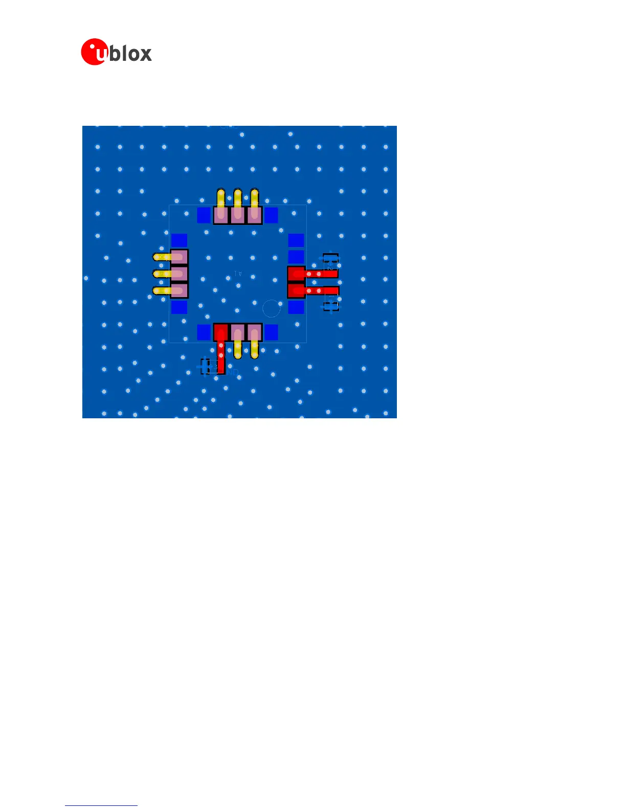
Figure 8: Layout recommendation (top layer)
SAM‑M8Q GNSS patch antenna module is intended to be placed in the middle of 50 x 50 mm GND size board,
but a larger or smaller ground plane can be used. When using smaller than 40 x 40 mm ground plane, the
performance may get decreased significantly.
Some important recommendations:
Easy to connect, but make sure all noisy lines / components are shielded or on inner layers
Do not place any noisy parts close to SAM-M8Q, place them as far away as possible or on other side of PCB
It is recommended not to place anything closer than 1 cm to each edge of SAM-M8Q
Performance goes significantly down if GND size is smaller than 40 x 40 mm
Use at least one layer for solid GND plane, preferably the layer SAM-M8Q is placed on it
Use solid GND plane under SAM-M8Q, which forms the shield. No signal traces allowed below SAM-M8Q
Route signal traces away from the module on top layer
When necessary, allow signal swap from top to bottom layer clearly away from module > 20 mm
Use copper pour ground planes on top and bottom layers; use multiple GND net via holes to tie separate
ground plane areas tightly together

 Loading...


