SARA-G3 series - System Integration Manual
UBX-13000995 - R06 Objective Specification System description
Page 40 of 218
1.6.2 Module power-off
The correct way to switch off SARA-G3 modules is by means of +CPWROFF AT command (more details
in
u-blox AT Commands Manual
[2]): in this way the current parameter settings are saved in the
module’s non-volatile memory and a proper network detach is performed.
An under-voltage shutdown occurs on SARA-G3 modules when the VCC supply is removed, but in this
case the current parameter settings are not saved in the module’s non-volatile memory and a proper
network detach cannot be performed.
An over-temperature or an under-temperature shutdown occurs when the temperature measured within the
wireless module reaches the dangerous area, if the optional Smart Temperature Supervisor feature is
activated and configured by the dedicated AT+USTS command. Refer to section 1.13.8 and to the
u-blox
AT Commands Manual
[2] for more details.
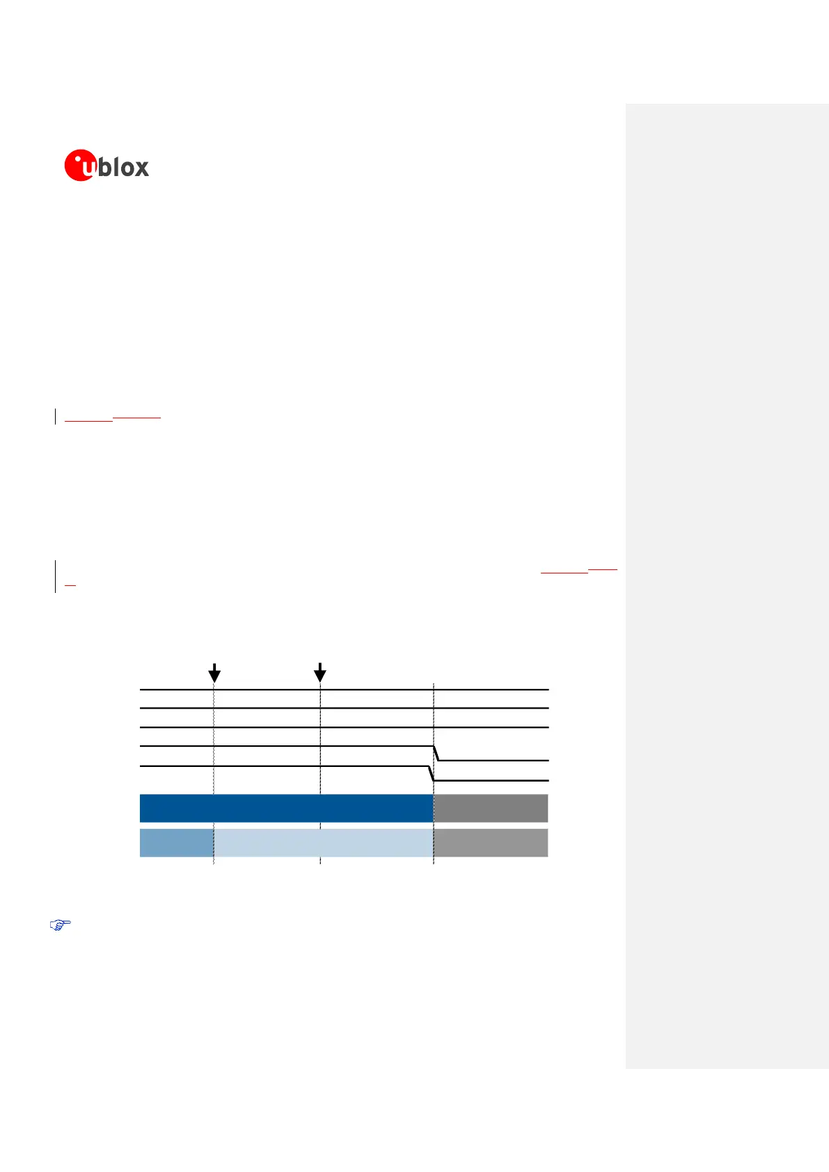
Figure 14Figure 14 describes the power-off sequence by means of +CPWROFF AT command. When the
+CPWROFF AT command is sent, the module starts the switch-off routine replying OK on the AT
interface. At the end of the switch-off routine, all digital pins are locked in tri-state by the module and
all the internal LDO voltage regulators except the RTC supply (V_BCKP) are turned off in a defined
power-off sequence. The module remains in power-off mode as long as a switch on event does not
occur (i.e. applying a low level on the PWR_ON pin, or by a pre-programmed RTC alarm), and enters
not-powered mode if the supply is removed from the VCC pin.
Current parameter settings are stored to the module’s non-volatile memory and a network detach is
performed before the OK reply from AT+CPWROFF command.
The duration of the switch-off routine phases can largely differ from the values reported in Figure 14Figure
14, depending on the network settings and the concurrent activities of the module performing a network
detach.
VCC
V_BCKP
PWR_ON
V_INT
Internal Reset
System State
BB Pads State Operational
Operational
→
Tristate / Floating
AT+CPWROFF
sent to the module
Figure 14: SARA-G3 series power-off sequence description
The Internal Reset signal is not available on a module pin, but the application can monitor the
V_INT pin to sense the end of the SARA-G3 series power-off sequence.
 Loading...