SARA-G3 series - System Integration Manual
UBX-13000995 - R06 Objective Specification System description
Page 41 of 218
1.6.3 Module reset
A SARA-G3 module reset can be performed in one of two ways.
RESET_N input pin: Forces a low level on the RESET_N input pin, causing an “external” or “hardware”
reset. This must be for at least 50 ms on SARA-G350 modules or 3000 ms on SARA-G300 and
SARA-G310 modules. This causes an asynchronous reset of the module baseband processor, excluding the
integrated Power Management Unit and the RTC internal block: the V_INT interfaces supply is enabled and
each digital pin is set in its reset state, the V_BCKP supply and the RTC block are enabled. Forcing an
“external” or “hardware” reset, the current parameter settings are not saved in the module’s non-volatile
memory and a proper network detach is not performed.
AT+CFUN command (refer to the
u-blox AT Commands Manual
[2] for more details): This command
causes an “internal” or “software” reset, which is an asynchronous reset of the module baseband
processor. The electrical behavior is the same as that of the “external” or “hardware” reset, but in an
“internal” or “software” reset the current parameter settings are saved in the module’s non-volatile
memory and a proper network detach is performed.
After either reset, when RESET_N is released from the low level, the module automatically starts its
power-on sequence from the reset state.
The reset state of all digital pins is reported in the pin description table in
SARA-G3 series
Data
Sheet
[1].
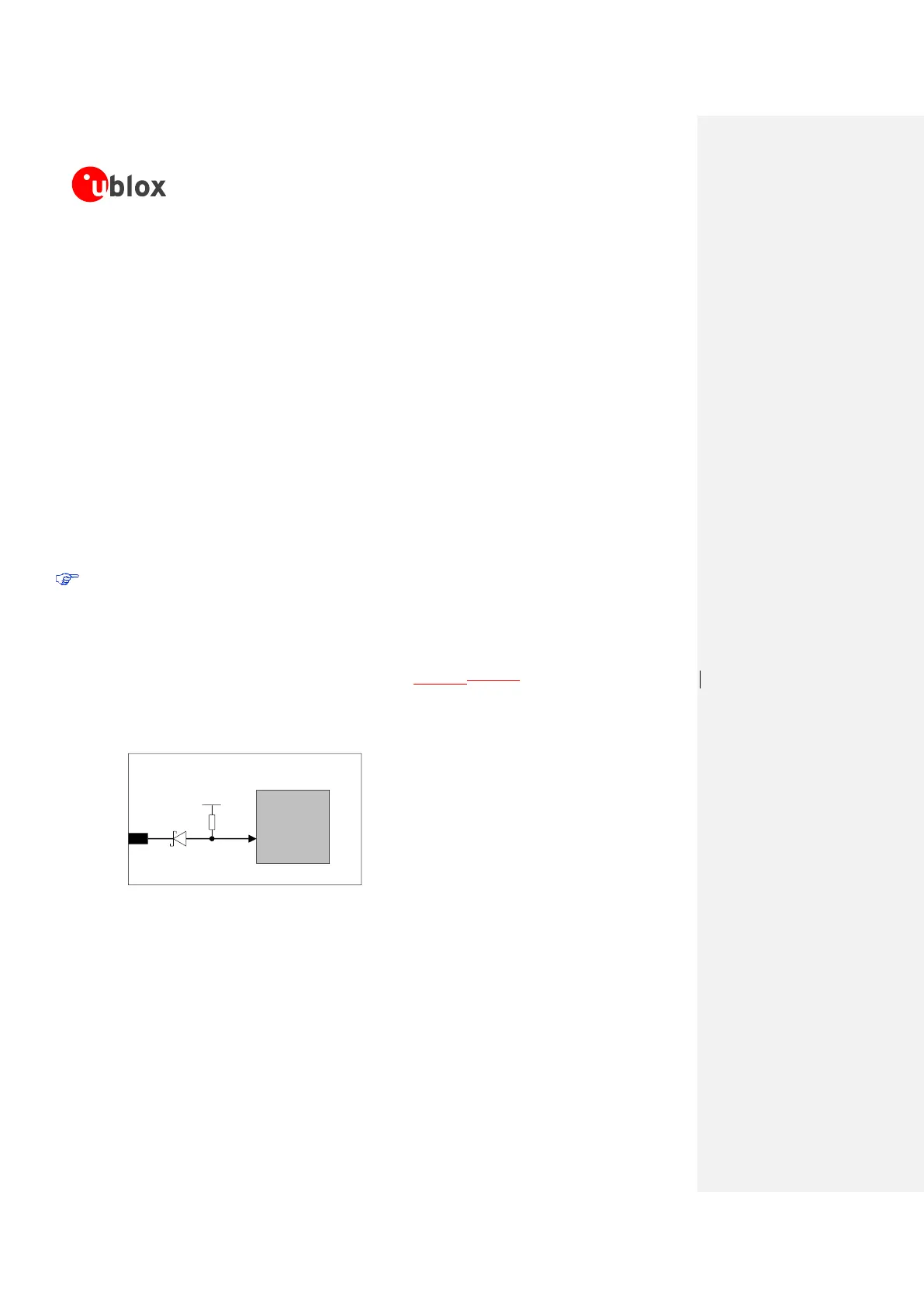
The electrical characteristics of RESET_N are different from the other digital I/O interfaces: the RESET_N
input pin is tolerant of voltages up to the module supply level due to the series Schottky diode mounted
inside the module on the RESET_N pin. As described in Figure 15Figure 15, the module has an internal
pull-up resistor which pulls the line to the high logic level when the RESET_N pin is not forced low from
the external. Detailed electrical characteristics are described in
SARA-G3 series
Data Sheet
[1].
Baseband
Processor
18
RESET_N
Reset Input
SARA-G3 series
10k
1.8 V
Figure 15: SARA-G3 series reset input (RESET_N) description
1.6.4 External 32 kHz signal input (EXT32K)
The EXT32K pin of SARA-G300 / SARA-G310 modules is an input pin that must be fed by a proper
32 kHz signal to make available the reference clock for the Real Time Clock (RTC) timing, used by the
module processor when in the low power idle-mode.
SARA-G300 / SARA-G310 modules can enter the low power idle-mode only if a proper 32 kHz signal
is provided at the EXT32K input pin, with power saving configuration enabled by the AT+UPSV command.
 Loading...