SARA-G3 series - System Integration Manual
UBX-13000995 - R06 Objective Specification Design-in
Page 130 of 218
2.5 Serial interfaces
2.5.1 Asynchronous serial interface (UART)
2.5.1.1 Guidelines for UART circuit design
Providing the full RS-232 functionality (using the complete V.24 link)
If RS-232 compatible signal levels are needed, two different external voltage translators (e.g. Maxim
MAX3237E and Texas Instruments SN74AVC8T245PW) can be used to provide full RS-232 (9 lines)
functionality. The Texas Instruments chip provides the translation from 1.8 V to 3.3 V, while the Maxim
chip provides the translation from 3.3 V to RS-232 compatible signal level.
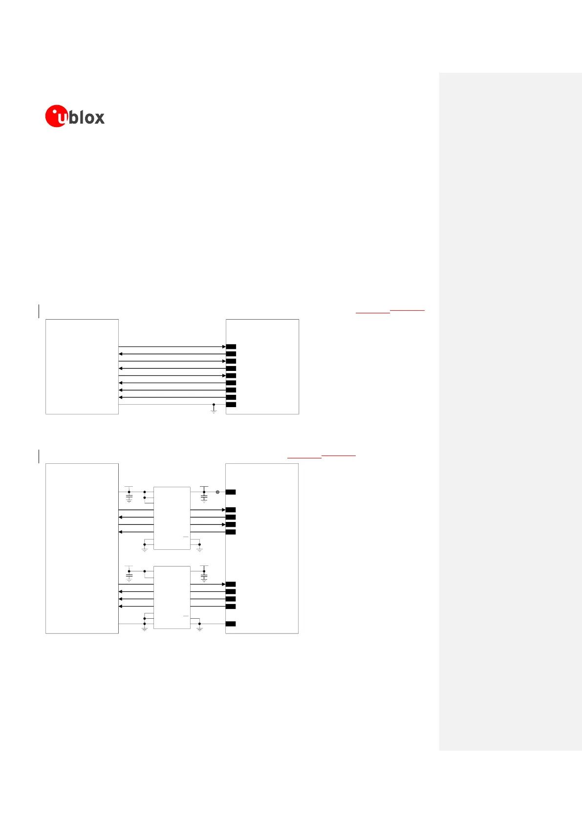
If a 1.8V application processor is used, for complete RS-232 functionality conforming to
ITU
Recommendation
[9] in DTE/DCE serial communication, the complete UART interface of the module
(DCE) must be connected to a 1.8 V application processor (DTE) as described in Figure 47Figure 47.
TxD
Application Processor
(1.8V DTE)
RxD
RTS
CTS
DTR
DSR
RI
DCD
GND
SARA-G3 series
(1.8V DCE)
12
TXD
9
DTR
13
RXD
10
RTS
11
CTS
6
DSR
7
RI
8
DCD
GND
Figure 47: UART interface application circuit with complete V.24 link in DTE/DCE serial communication (1.8V DTE)
If a 3.0 V Application Processor is used, appropriate unidirectional voltage translators must be provided
using the module V_INT output as 1.8 V supply, as described in Figure 48Figure 48.
4
V_INT
TxD
Application Processor
(3.0V DTE)
RxD
RTS
CTS
DTR
DSR
RI
DCD
GND
SARA-G3 series
(1.8V DCE)
12
TXD
9
DTR
13
RXD
10
RTS
11
CTS
6
DSR
7
RI
8
DCD
GND
1V8
B1 A1
GND
U1
B3A3
VCCBVCCA
Unidirectional
Voltage Translator
C1
C2
3V0
DIR3
DIR2 OE
DIR1
VCC
B2 A2
B4A4
DIR4
1V8
B1 A1
GND
U2
B3A3
VCCBVCCA
Unidirectional
Voltage Translator
C3
C4
3V0
DIR1
DIR3 OE
B2 A2
B4A4
DIR4
DIR2
TP
Figure 48: UART interface application circuit with complete V.24 link in DTE/DCE serial communication (3.0 V DTE)
 Loading...