SARA-G3 series - System Integration Manual
UBX-13000995 - R06 Objective Specification Design-in
Page 152 of 218
2.8 Reserved pins (RSVD)
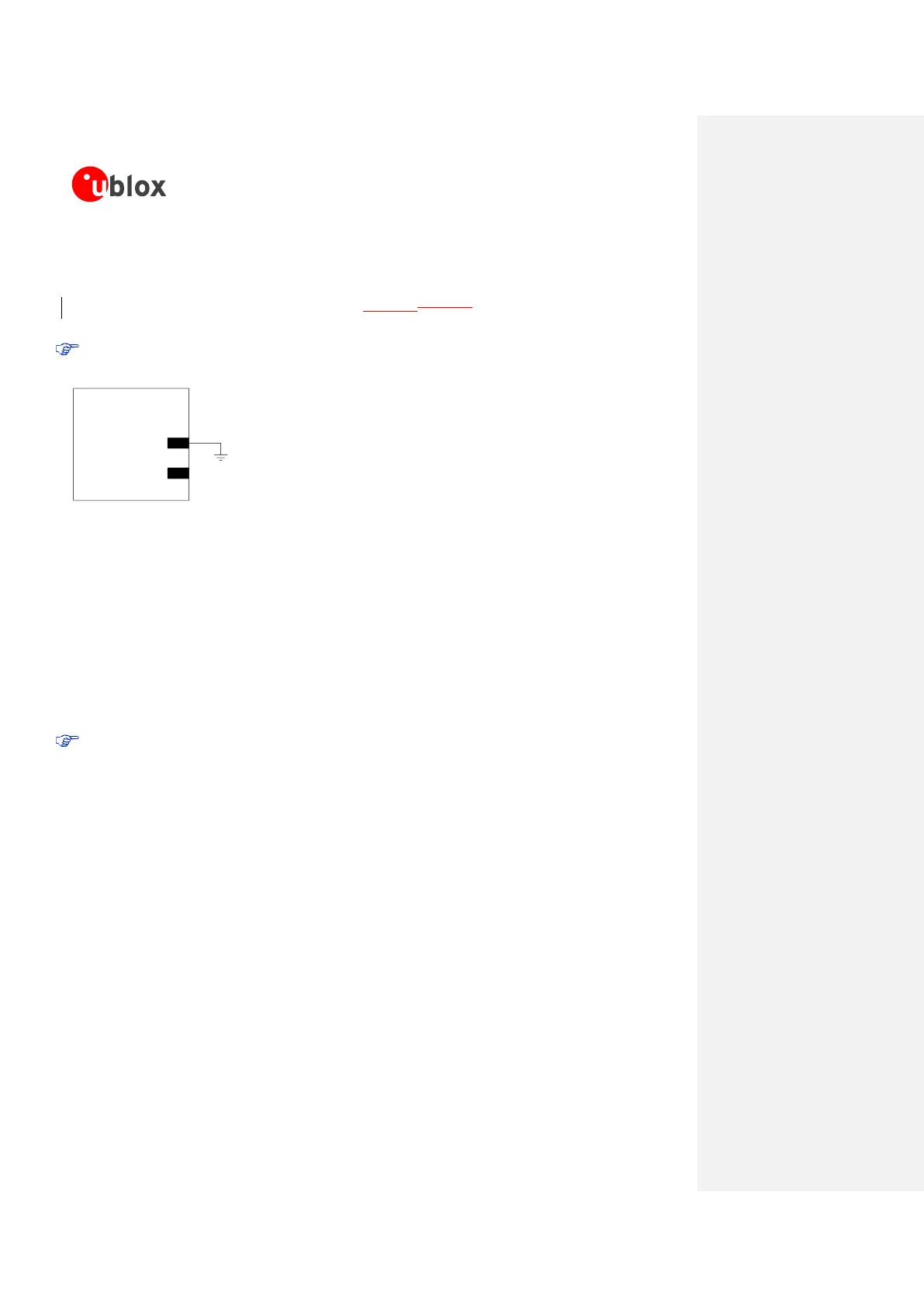
SARA-G3 series modules have pins reserved for future use. All the RSVD pins, except pin number 33,
can be left unconnected on the application board. Figure 62Figure 62 illustrates the application circuit.
Pin 33 (RSVD) must be connected to GND.
Figure 62: Application circuit for the reserved pins (RSVD)
2.9 Module placement
Optimize placement for minimum length of RF line and closer path from DC source for VCC.
Make sure that RF and analog circuits are clearly separated from any other digital circuits on the system
board.
Provide enough clearance between the module and any external part.
The heat dissipation during continuous transmission at maximum power can significantly raise the
temperature of the application base-board below the SARA-G3 modules: avoid placing temperature
sensitive devices close to the module.
 Loading...