SARA-G3 series - System Integration Manual
UBX-13000995 - R06 Objective Specification Design-in
Page 131 of 218
Part Number - Manufacturer
100 nF Capacitor Ceramic X7R 0402 10% 16 V
GRM155R61A104KA01 - Murata
Unidirectional Voltage Translator
SN74AVC4T774 - Texas Instruments
Table 27: Component for UART application circuit with complete V.24 link in DTE/DCE serial communication (3.0 V DTE)
Providing the TXD, RXD, RTS and CTS lines only (not using the complete V.24 link)
If the functionality of the DSR, DCD, RI and DTR lines is not required in, or the lines are not available:
Connect the module DTR input line to GND, since the module requires DTR active (low electrical
level)
Leave DSR, DCD and RI lines of the module unconnected and floating
If RS-232 compatible signal levels are needed, the Maxim 13234E voltage level translator can be used.
This chip translates voltage levels from 1.8 V (module side) to the RS-232 standard.
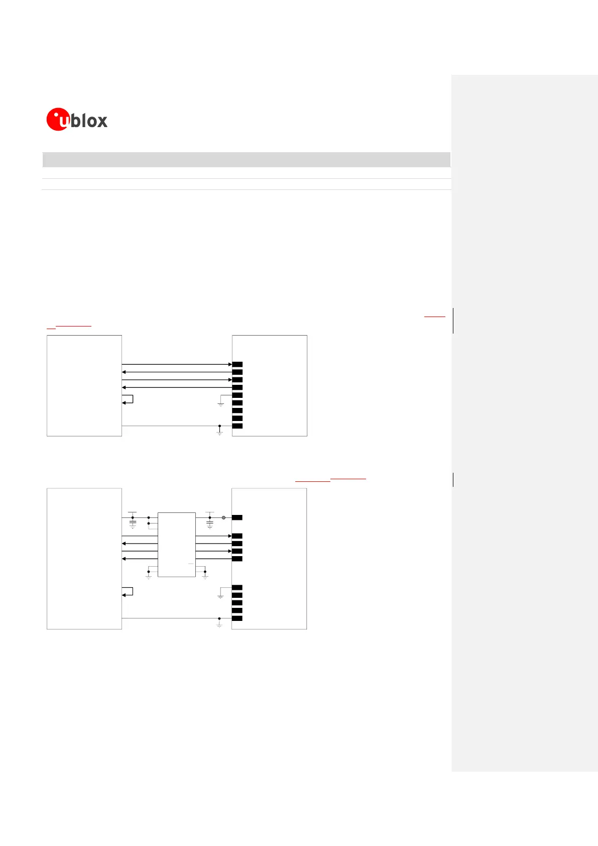
If a 1.8 V Application Processor is used, the circuit should be implemented as described in Figure
49Figure 49.
TxD
Application Processor
(1.8V DTE)
RxD
RTS
CTS
DTR
DSR
RI
DCD
GND
SARA-G3 series
(1.8V DCE)
12
TXD
9
DTR
13
RXD
10
RTS
11
CTS
6
DSR
7
RI
8
DCD
GND
Figure 49: UART interface application circuit with partial V.24 link (5-wire) in the DTE/DCE serial communication (1.8V DTE)
If a 3.0 V Application Processor is used, appropriate unidirectional voltage translators must be provided
using the module V_INT output as 1.8 V supply, as described in Figure 50Figure 50.
4
V_INT
TxD
Application Processor
(3.0V DTE)
RxD
RTS
CTS
DTR
DSR
RI
DCD
GND
SARA-G3 series
(1.8V DCE)
12
TXD
9
DTR
13
RXD
10
RTS
11
CTS
6
DSR
7
RI
8
DCD
GND
1V8
B1 A1
GND
U1
B3A3
VCCBVCCA
Unidirectional
Voltage Translator
C1
C2
3V0
DIR3
DIR2 OE
DIR1
VCC
B2 A2
B4A4
DIR4
TP
Figure 50: UART interface application circuit with partial V.24 link (5-wire) in DTE/DCE serial communication (3.0 V DTE)
 Loading...