Do you have a question about the U-Line CLRCO2075 and is the answer not in the manual?
Read all instructions completely before attempting to install or operate the unit.
Record model and serial number for information or service requests.
Complete and mail the Product Registration Card to validate warranty coverage.
Defines DANGER, WARNING, CAUTION, and IMPORTANT labels used in the manual.
Take off doors of old refrigerators/freezers to prevent child entrapment.
Never attempt repair until electricity is disconnected; altering cord voids warranty.
Use care when moving, avoid obstructing grille, clean condenser regularly.
Read instructions, connect water/drain by qualified plumber to avoid damage.
Plumbing installation must observe all state and local codes.
Failure to use specified pump may cause water leakage and damage.
Unit must be level and in a surrounding temperature of 50-110°F (10-40°C).
Electrical grounding required; do not remove prong or use extension cords.
All U-Line units have zero clearance for the door to open.
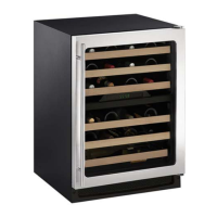
Stainless steel models require 2-1/2" handle clearance against a wall.
Install and connect the water supply line according to requirements.
Position unit for free air flow through the front grille.
Do not install unit behind closed doors.
Increase cabinet rough opening by 1/4" for easier unit installation and removal.
Review codes, use cold water, pressure 20-120 psi, install shut-off valve.
Allow extra water/drain line length for recessed installations for easier removal.
Turn on water, recheck for leaks, apply additional tightening if needed.
Unit must be level for even water flow, proper ice rate, and to prevent spills.
Remove top hinge pin and plastic screw plugs from new hinge location.
Remount top hinge and install door closers on the new bottom hinge location.
Remount bottom hinge and flip pivot plate over for reversal.
Align door pivot plate, install top hinge pin, and insert plastic screw plugs.
The top edge of the door should be 1/8" below the top of the cabinet, not flush.
Involves removing hinge pin, adjusting plate position, and reinstalling.
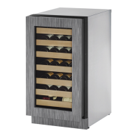
Covers door frame and handle for a built-in look. Requires optional kit.
Panel inserted into door frame to match decor. Max thickness 1/4".
Custom door panels must not weigh more than 20 lbs. Thickness must be 3/4".
Insert edges may be SHARP! Use care when installing.
Involves removing hinge pins, pulling gasket, and sliding panel insert.
The temperature controller will display even when the cycle selector switch is in OFF.
Plug in, check overflow tube, verify drain system, open water valve, set switch to ON.
Ice production stops until refrigerator reaches set point, then resumes.
Discard ice made during the first two to three hours of operation.
Press 'SET TEMP', then 'WARMER' or 'COOLER' to change set point.
Water circulates over evaporator, freezes, sediment drops, ice falls into bin.
Production rate affected by ambient temp, water temp, usage, cleanliness.
Explains dimples, variations, and slabbing of clear ice cubes.
Factory setting maintains 1/16"-1/8" ice bridge for optimal cube formation.
Disconnect power before making any ice thickness adjustments.
Remove front panel to access the ice cube thickness adjustment dial.
Turn dial clockwise (+) to thicken, counterclockwise (-) to thin ice bridge.
Pull shelf out, tilt edge up, and remove from unit.
Insert shelf at an angle over the rib to adjust position.
Steps for removing and installing door shelves.
Clean with mild detergent and warm water. Avoid solvent or abrasive cleaners.
Clean interior with mild soap solution, sanitize bin with bleach solution.
Do not use solvent cleaners on interior; they may transmit taste or damage finish.
Disconnect electric power before cleaning the condenser.
Do not touch condenser fins; they are SHARP and easily damaged.
Clean condenser coil using a soft brush or vacuum cleaner.
Use only U-Line cleaner; wear gloves/goggles; other cleaners void warranty.
Ice machine cleaner removes lime scale and other mineral deposits.
Refrigerator side does not operate during ice maker cleaning cycle. Remove fresh food.
Never use anything to force ice from the evaporator; damage may result.
Set switch to OFF, remove ice, remove cover, remove overflow tube.
Replace overflow tube, set switch to CLN, add cleaner to reservoir.
Reinstall cover, clean bin, sanitize bin, and resume ice production.
Ice production may take longer after cleaning; refrigeration takes precedence.
Clean solenoid valve inlet screen annually to ensure proper function.
Shut off water, disconnect power, clean screen with toothbrush, reconnect, verify drain.
Slide cover, swing down, pull away to remove. Replace with genuine U-Line bulb.
Cycle defrost models normally don't need manual defrosting, but may require it in high humidity.
Disconnect power before servicing. Failure to do so can result in death or shock.
Disconnect power, remove ice, shut off water, drain lines.
Drain all water if ambient temperature drops below 40°F to prevent freezing damage.
Clean the ice maker and storage bin before next use.
Prop door open to allow air circulation and prevent mold and mildew.
Always throw away ice made during the first 24 hours of operation when unit is returned to service.
Read normal operation and troubleshooting guide first to solve simple problems.
Never attempt repair or maintenance until main electrical power is disconnected.
Guide to identify problems, causes, and remedies for unit malfunctions.
Contact dealer, state Model/Serial Number, and explain the problem.
Check www.U-LineService.com if you do not know the selling dealer or service company.
| Brand | U-Line |
|---|---|
| Model | CLRCO2075 |
| Category | Refrigerator |
| Language | English |