Do you have a question about the ubbink Rolux and is the answer not in the manual?
Installation must conform with local codes and national fuel gas codes.
Use only Ubbink Rolux® vent system components; do not mix with other manufacturers.
Inspect each vent component for damage and correct seal placement before installation.
Guidelines for condensate management in vertical and horizontal terminations, including pitching.
Firmly press vent connections together with gaskets for an airtight seal; secure with screws.
Horizontal vent lengths over 5ft should pitch 1/4"/ft to the appliance to manage condensate.
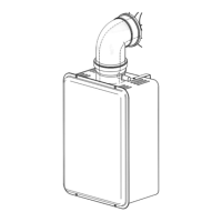
Instructions for connecting Ubbink Rolux® vent components to female appliance tops.
Use a condensate collector and trap to prevent backflow; ensure drain tube pitches down.
Determine and mark the vent location, considering appliance position and wall penetration.
Measure and cut vent pipes to fit, ensuring proper overlap and minimum pitch for horizontal runs.
Slide vent through wall, position wall plates, seal gaps, and secure the termination.
Determine roof discharge terminal location, considering roof angle and cutting appropriate hole size.
Shorten both the inside and outside pipes of the terminal to the correct length X.
Press vent connections together for an airtight seal and secure the system with pipe clamps.
Do not bury the enclosure below grade; ensure proper positioning above ground level.
Mount appliance as per instructions, mark wall, consider minimum distance above grade, and cut correct hole size.
Determine vent location considering appliance, water heater template, and minimum 2" above grade for wall passage.
Cut vent piece B to length, ensure extension A protrudes max 0.5" outside, and seal wall penetration.
Position enclosure cover over termination, slide to wall, seal ridge if needed, and secure with screws.
| Model | Rolux |
|---|---|
| Brand | Ubbink |
| Voltage | 230 V |
| Frequency | 50 Hz |
| Color | White |
| Material | Plastic |