MIA-M10Q-Integration manual
1.3 Pin assignment
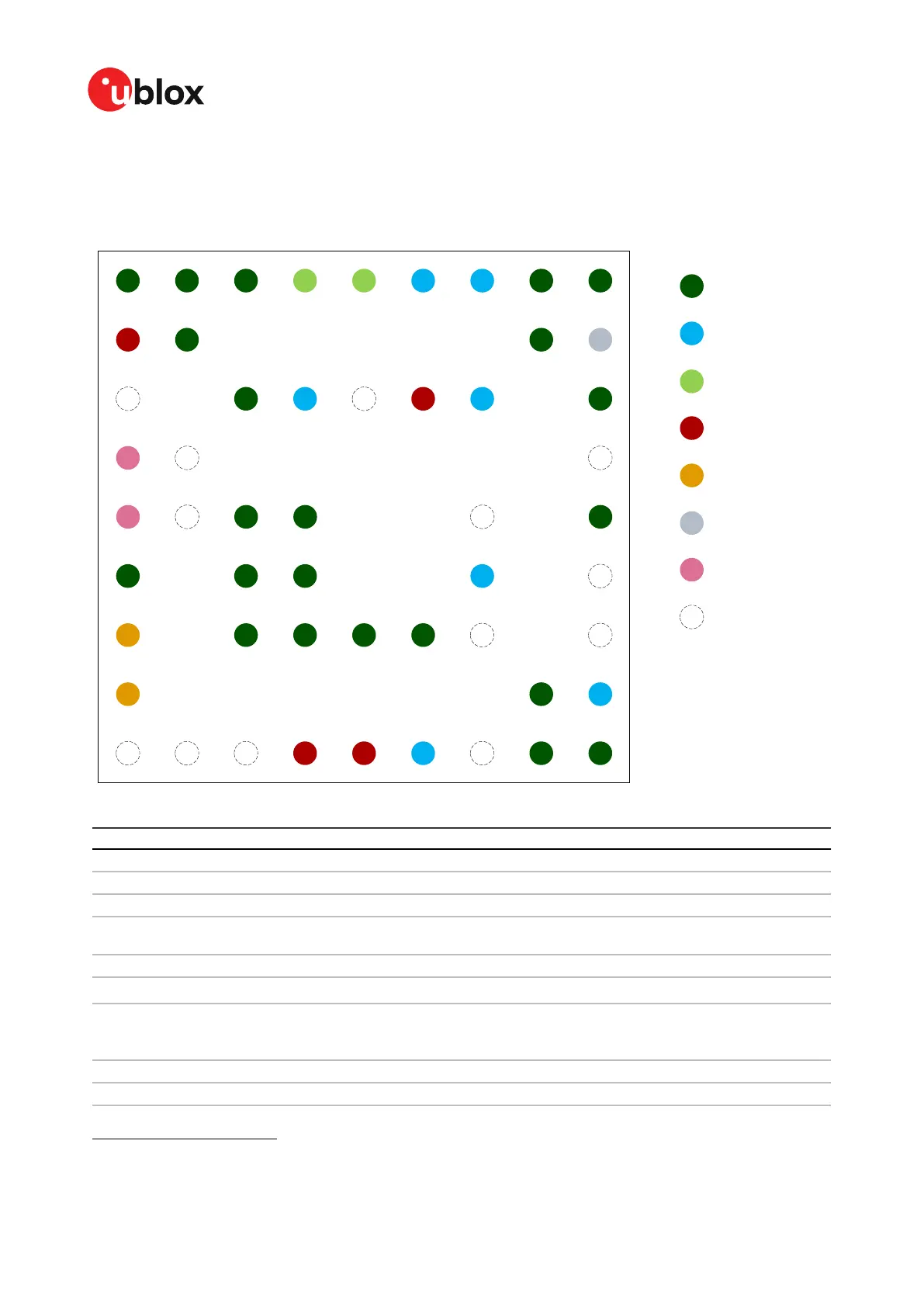
The pin assignment of the MIA-M10Q is shown below:
Figure 2: MIA-M10Q pin assignment
Pin no. Name PIO no. I/O Description Remarks
A1 GND - - - Connect to GND
A2 GND - - - Connect to GND
A3 GND - - - Connect to GND
A4 RTC_I - I RTC input
Leave open if not used. See Real-time clock for more
information.
A5 RTC_O - O RTC output Connect to GND if not used
A6 EXTINT 5 I/O External interrupt
See EXTINT for more information.
1
.
A7 TIMEPULSE 4 O Time pulse signal
See section TIMEPULSE for more information.
Alternative functions
1
. This pin is shared with
SAFEBOOT_N pin.
A8 GND - - - Connect to GND
A9 GND - - - Connect to GND
1
Alternatively, this pin can be used for ANT_DETECT, ANT_SHORT_N, TX_READY, and Data batching. Care must be taken
when the assigned function sets the pin as an output.
UBX-21028173 - R01
1 System description Page 7 of 89
C1-Public

 Loading...


