MIA-M10Q-Integration manual
Figure 36: Typical 1.8 V design
B.2 Antenna supervisor designs
Figure 37 and Figure 38 show a reference design for a 2-pin and 3-pin antenna supervisor design
respectively. Here are some key features:
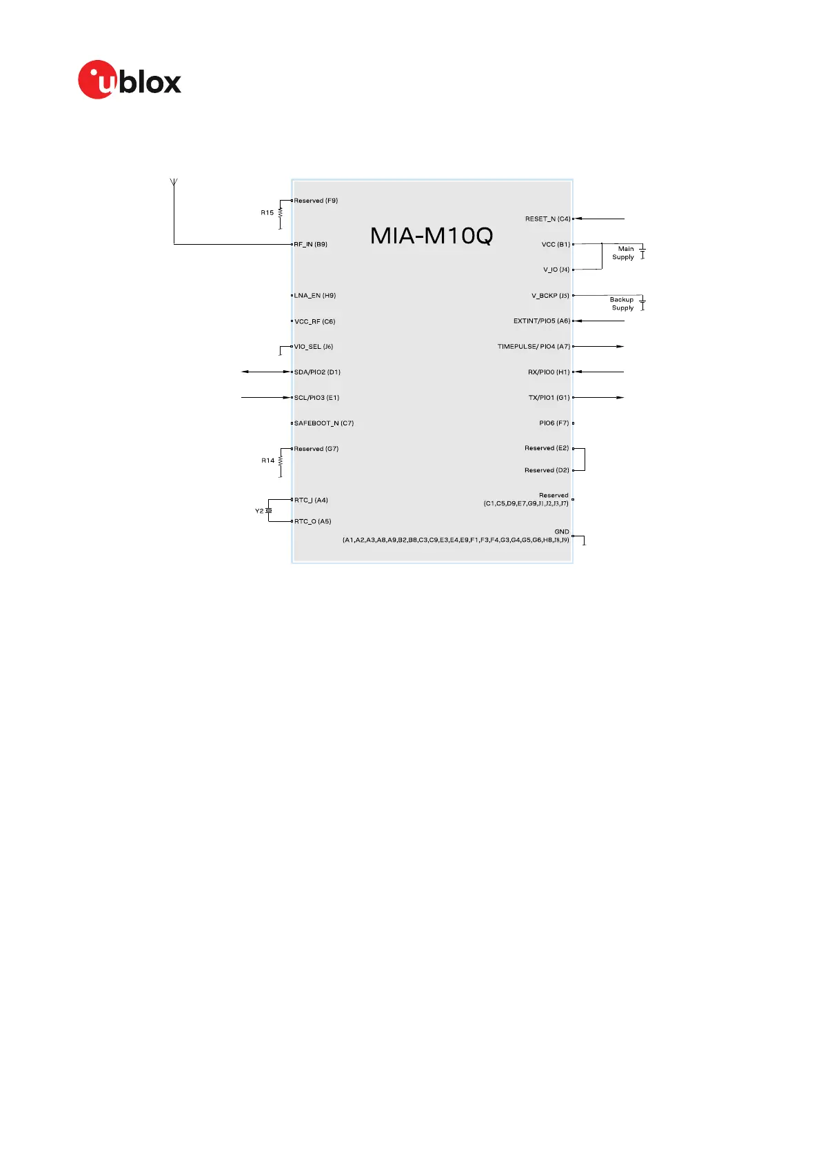
• VCC and V_IO are connected together to a single supply.
• Supply at V_BCKP is optional. If present, the hardware backup mode is supported. This mode
maintains the time and GNSS orbit data in the battery-backed RAM memory if the main supply
is switched off.
If there is no backup supply, the EXTINT pin can be used for time aiding and the GNSS orbit data
can be aided using AssistNow services or downloaded to the host and fed back to the receiver
at startup.
• An external SAW filter can be placed on the RF path as shown in Figure 37, which allows an SAW-
LNA-SAW RF front-end circuit for improving out-of-band immunity against RF interference from
other sources. This is especially useful when MIA-M10Q is used in cellular applications.
• An active antenna can be supplied with the VCC_RF output from MIA-M10Q or from an external
supply. VCC_RF is a filtered output voltage supply, which outputs VCC - 0.1 V. In addition, the
active antenna supply can be turned on/off by the LNA_EN signal, which also controls the internal
LNA of MIA-M10Q.
• External open drain buffers and operational amplifiers are also needed depending on whether a
2-pin or 3-pin antenna supervisor design is used.
UBX-21028173 - R01
Appendix Page 82 of 89
C1-Public

 Loading...


