MIA-M10Q-Integration manual
• UART and I2C communication interfaces are available. I2C PIOs (SDA and SCL) can be used in a
3-pin antenna supervisor design as shown in Figure 38. In this case, the I2C interface needs to be
disabled before assigning the new function to the PIOs.
Disable the I2C interface with the CFG-I2C-ENABLED configuration key when I2C pins are
used for antenna supervisor functions. Likewise, disable the UART interface (CFG-UART1-
ENABLED) or TIMEPULSE (CFG-TP-TP1_ENA) when the pins are used for antenna supervisor
functions.
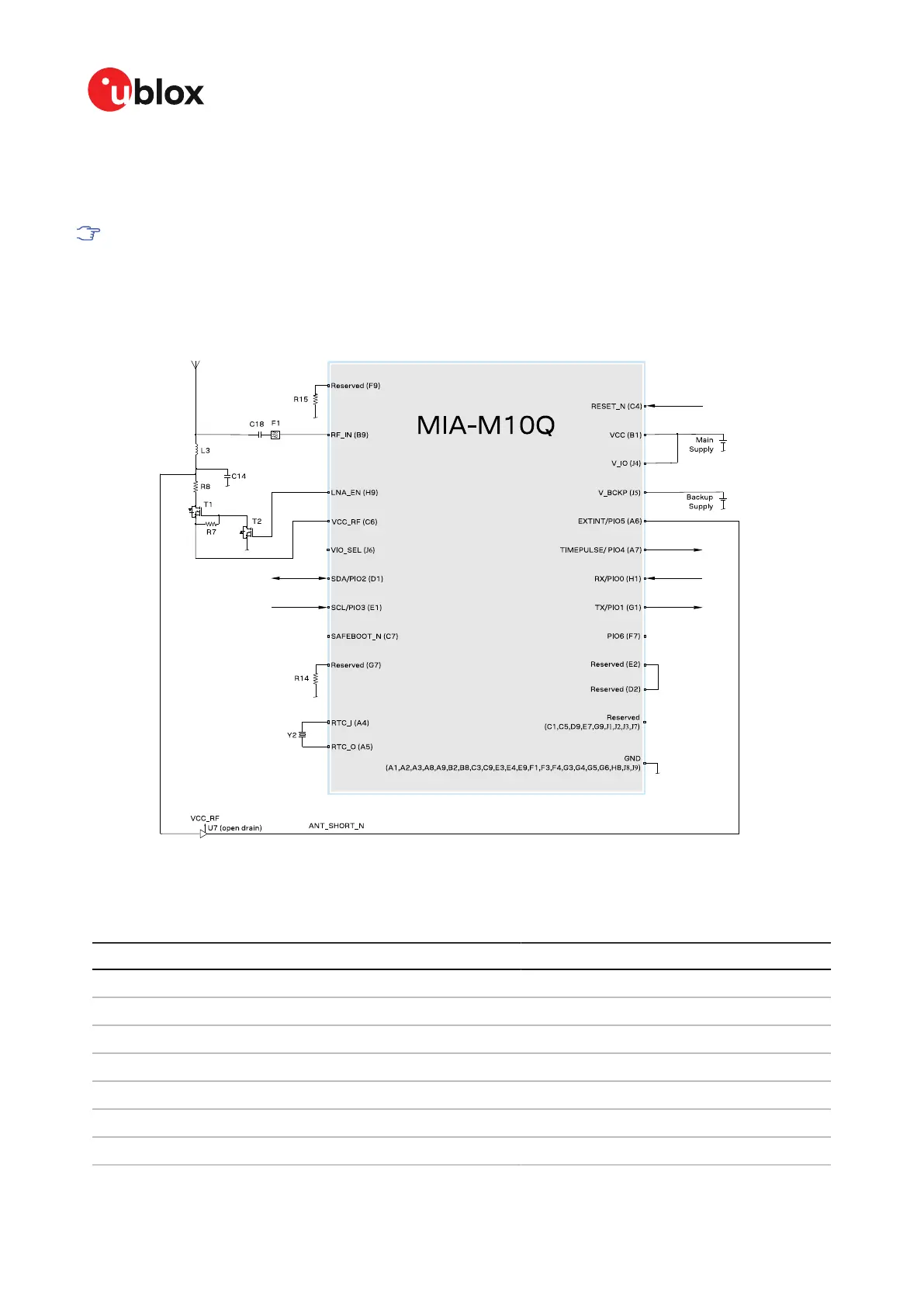
Figure 37: 2-pin antenna supervisor design
The 2-pin antenna supervisor configuration required for the Figure 37 reference design is listed in
Table 34.
Configuration key Value
CFG-HW-ANT_CFG_VOLTCTRL 1 (true), default (no configuration required)
CFG-HW-ANT_SUP_SWITCH_PIN 7, default (no configuration required)
CFG-HW-ANT_CFG_SHORTDET 1 (true)
CFG-HW-ANT_CFG_SHORTDET_POL 0 (false)
CFG-HW-ANT_SUP_SHORT_PIN 5
CFG-HW-ANT_CFG_PWRDOWN 1 (true)
CFG-HW-ANT_CFG_PWRDOWN_POL 0 (false), default (no configuration required)
UBX-21028173 - R01
Appendix Page 83 of 89
C1-Public

 Loading...


