NEO-8Q / NEO-M8 - Hardware integration manual
UBX-15029985 - Production information Hardware description Page 7 of 8
C1-Public
1.4.2 USB
A USB version 2.0 FS (Full Speed, 12 Mbit/s) compatible interface is available for communication as
an alternative to the UART. The USB_DP integrates a pull-up resistor to signal a full-speed device to
the host. The VDD_USB pin supplies the USB interface.
u-blox provides Microsoft® certified USB drivers for Windows 7, Windows 8 and Windows 10
operating systems. These drivers are available at our website at www.u-blox.com
USB external components
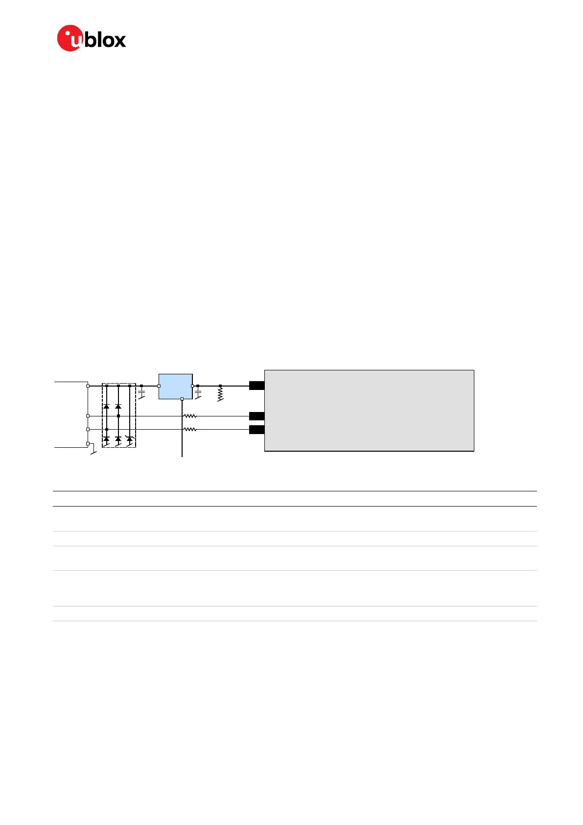
The USB interface requires some external components to implement the physical characteristics
required by the USB 2.0 specification. These external components are shown in Figure 2 and listed in
Table 1. To comply with USB specifications, VBUS must be connected through an LDO (U1) to pin
VDD_USB on the module.
In USB self-powered mode, the power supply (VCC) can be turned off and the digital block is not
powered. In this case, since VBUS is still available, the USB host would still receive the signal indicating
that the device is present and ready to communicate. This should be avoided by disabling the LDO
(U1) using the enable signal (EN) of the VCC-LDO or the output of a voltage supervisor. Depending on
the characteristics of the LDO (U1) it is recommended to add a pull-down resistor (R11) at its output
to ensure VDD_USB is not floating if the LDO (U1) is disabled or the USB cable is not connected, that
is, VBUS is not supplied.
☞ USB bus-powered mode is not supported.
Module
VDD_USB
LDO
VDD_USB
R4
USB_DP
USB_DM
R5
C24 C23
D2
VBUS
DP
DM
GND
USB Device Connector
U1
EN
R11
EN
Figure 2: USB interface
Name Component Function Comments
U1 LDO
Regulates VBUS (4.4 …5.25 V)
down to a voltage of 3.3 V.
Almost no current requirement (~1 mA) if the GNSS receiver is
operated as a USB self-powered device.
C23, C24 Capacitors Required according to the specification of LDO U1
D2
Protection
diodes
Protect circuit from overvoltage /
ESD when connecting.
Use low capacitance ESD protection such as ST Microelectronics
USBLC6-2.
R4, R5
Serial
termination
resistors
Establish a full-speed driver
impedance of 28…44 Ω
A value of 27 Ω is recommended.
R11 Resistor
100 kΩ is recommended for USB self-powered setup.
Table 1: Summary of USB external components
1.4.3 Display Data Channel (DDC)
An I2C compatible Display Data Channel (DDC) interface is available on NEO-8Q and NEO-M8 series
modules for serial communication with an external host CPU. The interface only supports operation
in slave mode (master mode is not supported). The DDC protocol and electrical interface are fully
compatible with the Fast-Mode of the I2C industry standard. DDC pins SDA and SCL have internal
pull-up resistors.
 Loading...


