NEO-8Q / NEO-M8 - Hardware integration manual
UBX-15029985 - Production information Hardware description Page 6 of 7
C1-Public
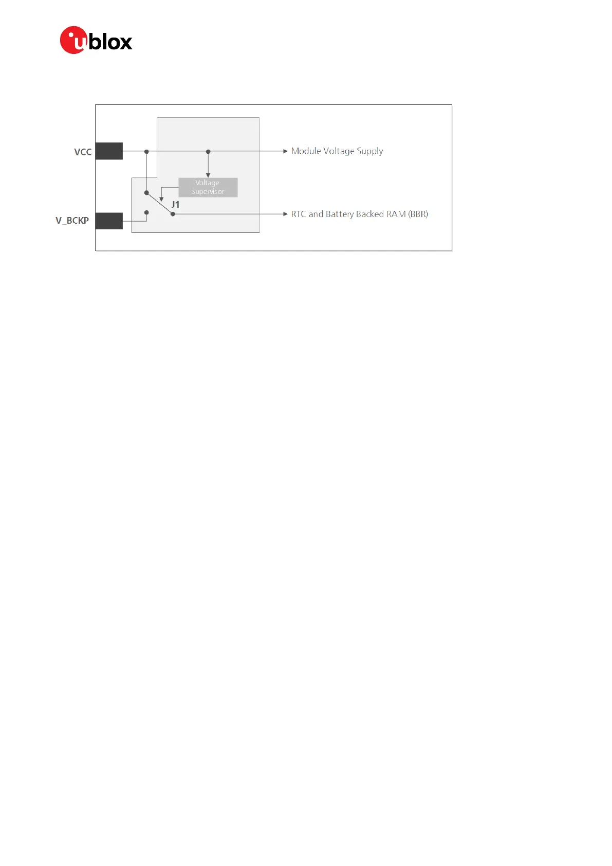
Figure 1: Backup battery and voltage (for exact pin orientation, see the corresponding product data sheet)
☞ Avoid high resistance on the V_BCKP line: During the switch from main supply to backup supply,
a short current adjustment peak can cause high voltage drop on the pin with possible
malfunctions.
☞ If no backup supply voltage is available, connect the V_BCKP pin to VCC.
☞ As long as power is supplied to the NEO-8Q and NEO-M8 series modules through the VCC pin, the
backup battery is disconnected from the RTC and the BBR to avoid unnecessary battery drain (see
Figure 1). In this case, VCC supplies power to the RTC and BBR.
Real-Time Clock (RTC)
The RTC is driven by a 32 kHz oscillator using an RTC crystal. If the main supply voltage fails, and a
battery is connected to V_BCKP, parts of the receiver switch off, but the RTC still runs providing a
timing reference for the receiver. This operating mode is called Hardware Backup Mode, which enables
all relevant data to be saved in the backup RAM to allow a hot or warm start later.
1.3.3 VDD_USB: USB interface power supply
VDD_USB supplies the USB interface. If the USB interface is not used, the VDD_USB pin must be
connected to GND. For more information about correctly handling the VDD_USB pin, see section 1.4.
1.3.4 VCC_RF: Output voltage RF
The VCC_RF pin can supply an active antenna or external LNA. For more information, see section 2.4.
1.4 Interfaces
1.4.1 UART
The NEO-8Q and NEO-M8 series modules include a Universal Asynchronous Receiver Transmitter
(UART) serial interface RXD/TXD supporting configurable baud rates. The baud rates supported are
specified in the corresponding product data sheet.
The signal output and input levels are 0 V to VCC. An interface based on RS232 standard levels (+/-
12 V) can be implemented using level shifters such as Maxim MAX3232. Hardware handshake signals
and synchronous operation are not supported.
☞ Designs must allow access to the UART pin for future service and reconfiguration.

 Loading...


