SARA-R4/N4 series - System Integration Manual
UBX-16029218 - R11 System description Page 25 of 157
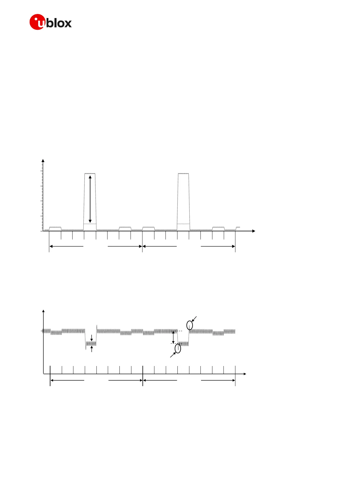
slot/burst) with a periodicity of 4.615 ms (width of 1 frame = 8 slots/burst), that is, with a 1/8 duty cycle
according to GSM TDMA (Time Division Multiple Access).
If the module is transmitting in 2G single-slot mode in the 1800 or 1900 MHz bands, the current
consumption figures are much lower than during transmission in the low bands, due to the 3GPP transmitter
output power specifications.
During a 2G call, current consumption is not significantly high while receiving or in monitor bursts, and it
is low in the bursts unused to transmit / receive.
Figure 5 shows an example of the module current consumption profile versus time in 2G single-slot.
Time
[ms]
RX
slot
unused
slot
unused
slot
TX
slot
unused
slot
unused
slot
MON
slot
unused
slot
RX
slot
unused
slot
unused
slot
TX
slot
unused
slot
unused
slot
MON
slot
unused
slot
GSM frame
4.615 ms
(1 frame = 8 slot s)
Current [A]
200 mA
60-120 mA
1900 mA
Peak current depends
on TX power and
actual antenna load
GSM frame
4.615 ms
(1 frame = 8 slot s)
1.5
1.0
0.5
0.0
2.0
60-120 mA
10 -40 m A
Figure 5: VCC current consumption profile versus time during a GSM call (1 TX slot, 1 RX slot)
Figure 6 illustrates the VCC voltage profile versus time during a 2G single-slot call, according to the related
VCC current consumption profile described in Figure 5.
Time
undershoot
overshoot
ripple
drop
Voltage
3.8 V
(t yp)
RX
slot
unused
slot
unused
slot
TX
slot
unused
slot
unused
slot
MON
slot
unused
slot
RX
slot
unused
slot
unused
slot
TX
slot
unused
slot
unused
slot
MON
slot
unused
slot
GSM frame
4.615 ms
(1 frame = 8 slots)
GSM frame
4.615 ms
(1 frame = 8 slot s)
Figure 6: Description of the VCC voltage profile versus time during a 2G single-slot call (1 TX slot, 1 RX slot)
When a GPRS connection is established, more than one slot can be used to transmit and/or more than one
slot can be used to receive. The transmitted power depends on network conditions, which set the peak
 Loading...


