SARA-R4/N4 series - System Integration Manual
UBX-16029218 - R11 Design-in Page 55 of 157
Power capability: the switching regulator with its output circuit must be capable of providing a voltage
value to the VCC pins within the specified operating range and must be capable of delivering to VCC
pins the maximum current consumption occurring during transmissions at the maximum power, as
specified in the SARA-R4/N4 series Data Sheet [1].
Low output ripple: the switching regulator together with its output circuit must be capable of providing
a clean (low noise) VCC voltage profile.
High switching frequency: for best performance and for smaller applications it is recommended to
select a switching frequency ≥ 600 kHz (since L-C output filter is typically smaller for high switching
frequency). The use of a switching regulator with a variable switching frequency or with a switching
frequency lower than 600 kHz must be carefully evaluated since this can produce noise in the VCC
profile and therefore negatively impact modulation spectrum performance.
PWM mode operation: it is preferable to select regulators with Pulse Width Modulation (PWM) mode.
While in connected mode, the Pulse Frequency Modulation (PFM) mode and PFM/PWM modes
transitions must be avoided to reduce noise on VCC voltage profile. Switching regulators can be used
that are able to switch between low ripple PWM mode and high ripple PFM mode, provided that the
mode transition occurs when the module changes status from the active mode to connected mode. It
is permissible to use a regulator that switches from the PWM mode to the burst or PFM mode at an
appropriate current threshold.
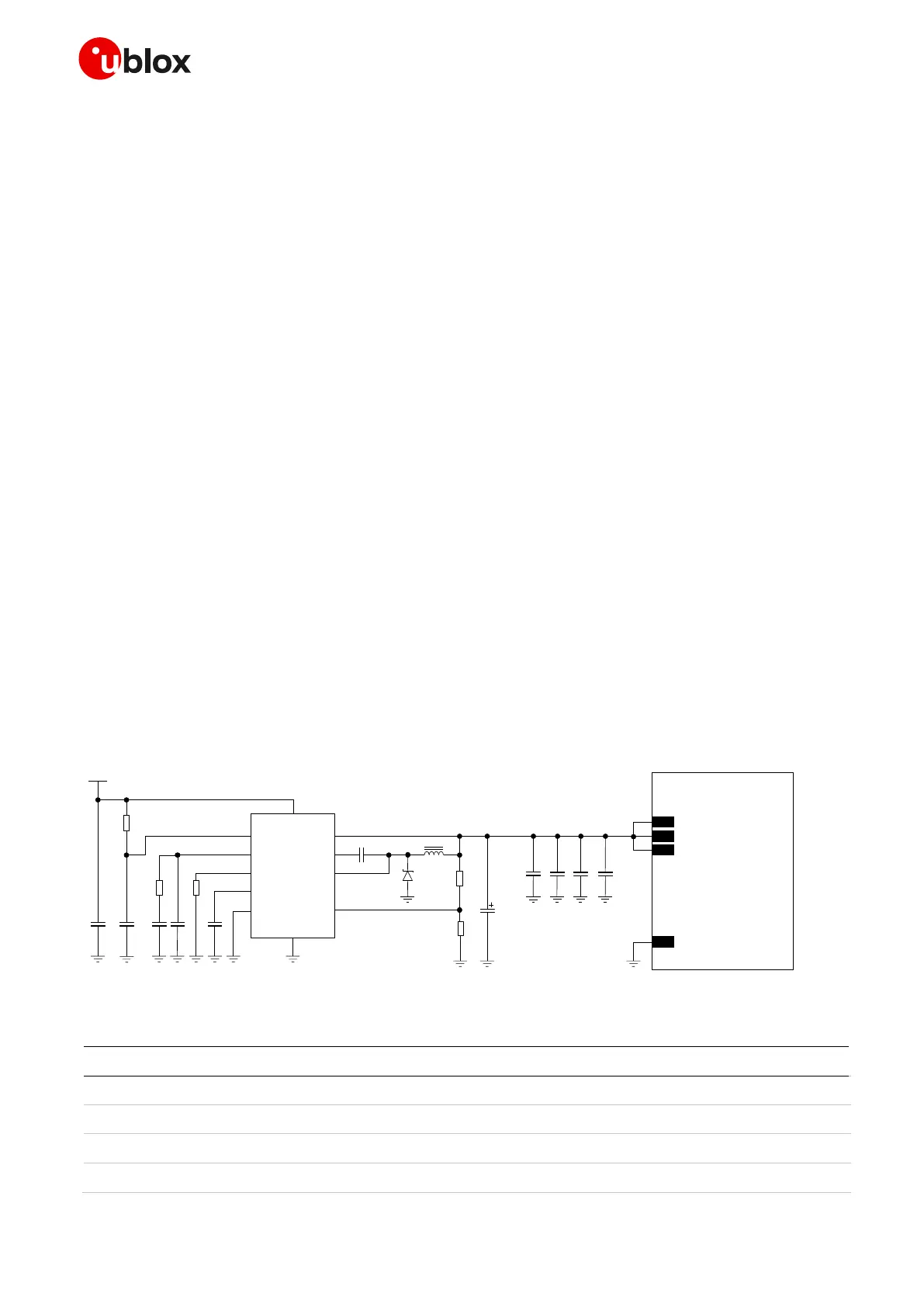
Figure 16 and the components listed in Table 9 show an example of a high reliability power supply circuit
for the SARA-R412M modules that support 2G radio access technology. This circuit is also suitable for the
other SARA-R4/N4 series modules, where the module VCC input is supplied by a step-down switching
regulator capable of delivering the highest peak / pulse current specified for the 2G use-case, with low
output ripple and with fixed switching frequency in PWM mode operation greater than 1 MHz.
SARA-R4/N4
12V
C5
R3
C4
R2
C2C1
R1
VIN
RUN
VC
RT
PG
SYNC
BD
BOOST
SW
FB
GND
6
7
10
9
5
C6
1
2
3
8
11
4
C7
C8
D1
R4
R5
L1
C3
U1
52
VCC
53
VCC
51
VCC
GND
C9 C10 C11
Figure 16: Example of high reliability VCC supply circuit for SARA-R4/N4 series modules, using a step-down regulator
Part Number - Manufacturer
10 µF Capacitor Ceramic X7R 5750 15% 50 V
10 nF Capacitor Ceramic X7R 0402 10% 16 V
680 pF Capacitor Ceramic X7R 0402 10% 16 V
22 pF Capacitor Ceramic C0G 0402 5% 25 V
 Loading...


