SARA-R4/N4 series - System Integration Manual
UBX-16029218 - R11 Design-in Page 83 of 157
Ensure solid metal connection of the adjacent metal layer on the PCB stack-up to main ground layer,
providing enough vias on the adjacent metal layer, as described in Figure 34,
Route RF transmission lines far from any noise source (as switching supplies and digital lines) and from
any sensitive circuit (as USB),
Avoid stubs on the transmission lines,
Avoid signal routing in parallel to transmission lines or crossing the transmission lines on buried metal
layer,
Do not route microstrip lines below discrete component or other mechanics placed on top layer
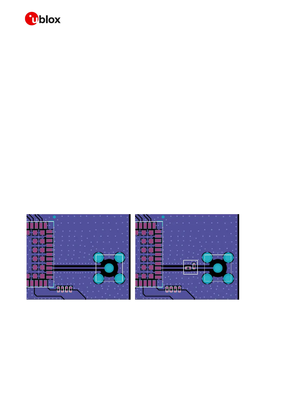
Two examples of a suitable RF circuit design are illustrated in Figure 34, where the antenna detection circuit
is not implemented (if the antenna detection function is required by the application, follow the guidelines
for circuit and layout implementation detailed in section 2.4.2):
In the first example shown on the left, the ANT pin is directly connected to an SMA connector by means
of a suitable 50 transmission line, designed with the appropriate layout.
In the second example shown on the right, the ANT pin is connected to an SMA connector by means
of a suitable 50 transmission line, designed with the appropriate layout, with an additional high pass
filter to improve the ESD immunity at the antenna port. (The filter consists of a suitable series capacitor
and shunt inductor, for example the Murata GRM1555C1H150JA01 15 pF capacitor and the Murata
LQG15HN39NJ02 39 nH inductor with Self-Resonant Frequency ~1 GHz.).
SARA module
SM A
connect or
SARA module
SM A
connect or
High-pass filt er
t o im prove
ESD im munit y
Figure 34: Example of circuit and layout for antenna RF circuits on the application board
Guidelines for RF termination design
The RF termination must provide a characteristic impedance of 50 as well as the RF transmission line up
to the RF termination, to match the characteristic impedance of the ANT port.
 Loading...


