SARA-R4/N4 series - System Integration Manual
UBX-16029218 - R11 Design-in Page 99 of 157
Part Number - Manufacturer
100 nF Capacitor Ceramic X7R 0402 10% 16 V
GRM155R61A104KA01 - Murata
Unidirectional Voltage Translator
SN74AVC4T774
13
- Texas Instruments
Table 29: Component for UART application circuit with complete V.24 link in DTE/DCE serial communication (3.0 V DTE)
Providing the TXD, RXD, RTS, CTS and DTR lines only
If the functionality of the DSR, DCD and RI lines is not required, or the lines are not available:
Leave DSR, DCD and RI lines of the module floating, with a test-point on DCD
If RS-232 compatible signal levels are needed, two different external voltage translators (e.g. Maxim
MAX3237E and Texas Instruments SN74AVC4T774) can be used. The Texas Instruments chips provide the
translation from 1.8 V to 3.3 V, while the Maxim chip provides the translation from 3.3 V to RS-232
compatible signal level.
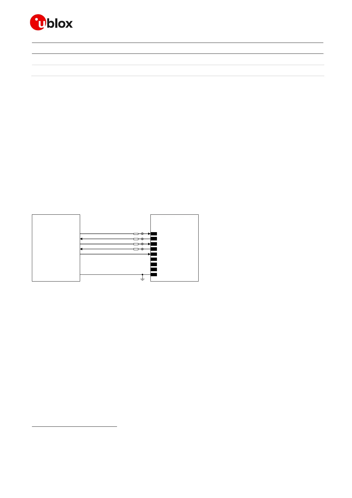
Figure 42 describes the circuit that should be implemented as if a 1.8 V Application Processor (DTE) is used,
given that the DTE will behave correctly regardless of the DSR input setting.
TxD
Application Processor
(1.8V DTE)
RxD
RTS
CTS
DTR
DSR
RI
DCD
GND
SARA-R4/N4
(1.8V DCE)
12
TXD
9
DTR
13
RXD
10
RTS
11
CTS
6
DSR
7
RI
8
DCD
GND
0 Ω
0 Ω
TP
TP
0 Ω
0 Ω
TP
TP
Figure 42: UART interface application circuit with partial V.24 link (6-wire) in the DTE/DCE serial communication (1.8 V DTE)
If a 3.0 V Application Processor (DTE) is used, then it is recommended to connect the 1.8 V UART interface
of the module (DCE) by means of appropriate unidirectional voltage translators using the module V_INT
output as 1.8 V supply for the voltage translators on the module side, as described in Figure 43, given that
the DTE will behave correctly regardless of the DSR input setting.
Voltage translator providing partial power down feature so that the DTE 3 V supply can be also ramped up before V_INT 1.8 V supply
Flow control is not supported by ‘00’, ‘01’ and SARA-R410M-02B product versions, but the RTS input must be set low to use the UART on
‘00’ and ‘01’ versions. The DTR input must be set low to have URCs presented over UART on ‘00’, ‘01’ and ‘x2’ product versions.
 Loading...


