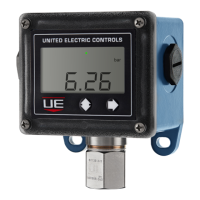
IM_1XSW-02
www.ueonline.com
2
Non-Incendive - Model 1XSWLL, 1XSWHL and 1XSWHH
N. America Europe International
Cert number: UL File E226592 DEMKO 15 ATEX 1483 IECEx UL 08.0017X
Applicable
Standards
UL-60079-0, UL 60079-15, ISA 12.12.01,
CSA C22.2 No. 157-92, CSA C22.2 No.
213, CSA C22.2 No. 60079-0:11, CSA
C22.2 No. 60079-15:12
EN 60079-0:2012 +
A11:2013
EN 60079-15:Ed.10
IEC 60079-
0:Ed.6(2011-06) +
Corr.1 (2012-01) +
Corr.2 (2013-12)
IEC 60079-15:Ed.4
Suitable for ap-
propriate use in:
Class I, Div. 2, Groups A, B, C & D
Class II, Div. 2 Groups F & G
Class III
Class I, Zone 2 AEx nA IIC T5
Ex nA IIC T5
II 3 G Ex nA IIC T4 Gc Ex nA IIC T4 Gc
FLAMEPROOF - SPECIAL CONDITIONS FOR SAFE USE
• Field wiring must be rated 105°C minimum. For ambient temperatures below -10°C, use suitable field wiring.
• Blanking elements from factory have been tested for flameproof “d” and dust “tb” with the enclosure as an assembly and carry no
markings.
• A suitable thermowell made from corrosion-resistant material and engaging 5 threads minimum (with thread sealant) is required for
the local spring loaded temperature sensor to maintain IP66
Flameproof joint and gap details
– Enclosure to cover threaded joint: 4” - 16 UN-2, 7 threads engaged minimum
– Glass to cover cemented joint: 0.753” (19.1 mm) rabbet/spigot minimum length
– Breather element threaded joint: M8-1.25 (6g/6H medium fit class), 11 threads engaged minimum
– Electrical conduit threaded joint: 3/4”-14 NPT, 5 threads engaged minimum
– Enclosure to sensor threaded joint:
• Pressure models: 1”-20 UNEF-2, 10 threads engaged minimum
• Temperature models: 1/2”-14 NPT, 5 threads engaged minimum
• Remote and local spring loaded temperature sensor gap joints: 0.0045” (0.114 mm) maximum annular gap by
1.25” (31.8 mm) minimum length
• The Unit must be cleaned with a damp cloth to avoid static discharge.
Dual Seal Adaptor (Option M041)
• Threaded Dual Seal Adaptor Option Enclosure to One Series Enclosure : 1”-20 UNEF-2, 10 threads engaged minimum
• Breather element threaded joint: 1/4”-20 UNC-2, 10 threads engaged minimum
• Secondary Seal Housing to union housing joint: 0 .580” (14.73 mm) rabbet/spigot minimum length, maximum annular gap 0.003
in. (0.08 mm)
• Sensor to union housing joint: 0 .580” (14.73 mm) rabbet/spigot minimum length, maximum gap 0.003 in. (0.08 mm)
• Threaded Dual Seal Adaptor option to Sensor 1”-20 UNEF-2, 10 threads engaged minimum or 1/2”-14 NPT 5 threads engaged
minimum.
INTRINSIC SAFETY - SPECIAL CONDITIONS FOR SAFE USE
• Enclosure and cover are made from Aluminum Alloy, do not strike with heavy object.
• Separation distances were assessed to Annex F.
• Device must be powered by a galvanically isolated intrinsic safety barrier.
Table 1

 Loading...