IM_1XSW-02
www.ueonline.com
7
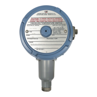
Models 1XSWLL and 1XSWHL can also be wired in series with the coil of certain interposing relays, as shown in figures 6-7. The relay coil
specifications must not exceed the maximum switch ratings. (See Table 2, page 6).
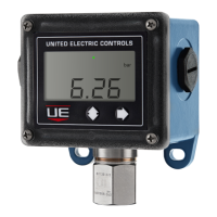
NOTE: For bench testing model 1XSWLL, a circuit is required as shown in figure 8. These components are not included and must be provided
by the user. Do not connect model 1XSWLL directly to a power supply without a suitable load in series with the switch. Do not
exceed the maximum switch ratings or permanent damage may result (See table 2 on page 6).
5W min.
24 VDC
1.8KΩ
LED
Recommended
Bench Test
Circuit
70-240 VAC
L1/H
Common
1XSWLL
1XSWHL
Figure 8
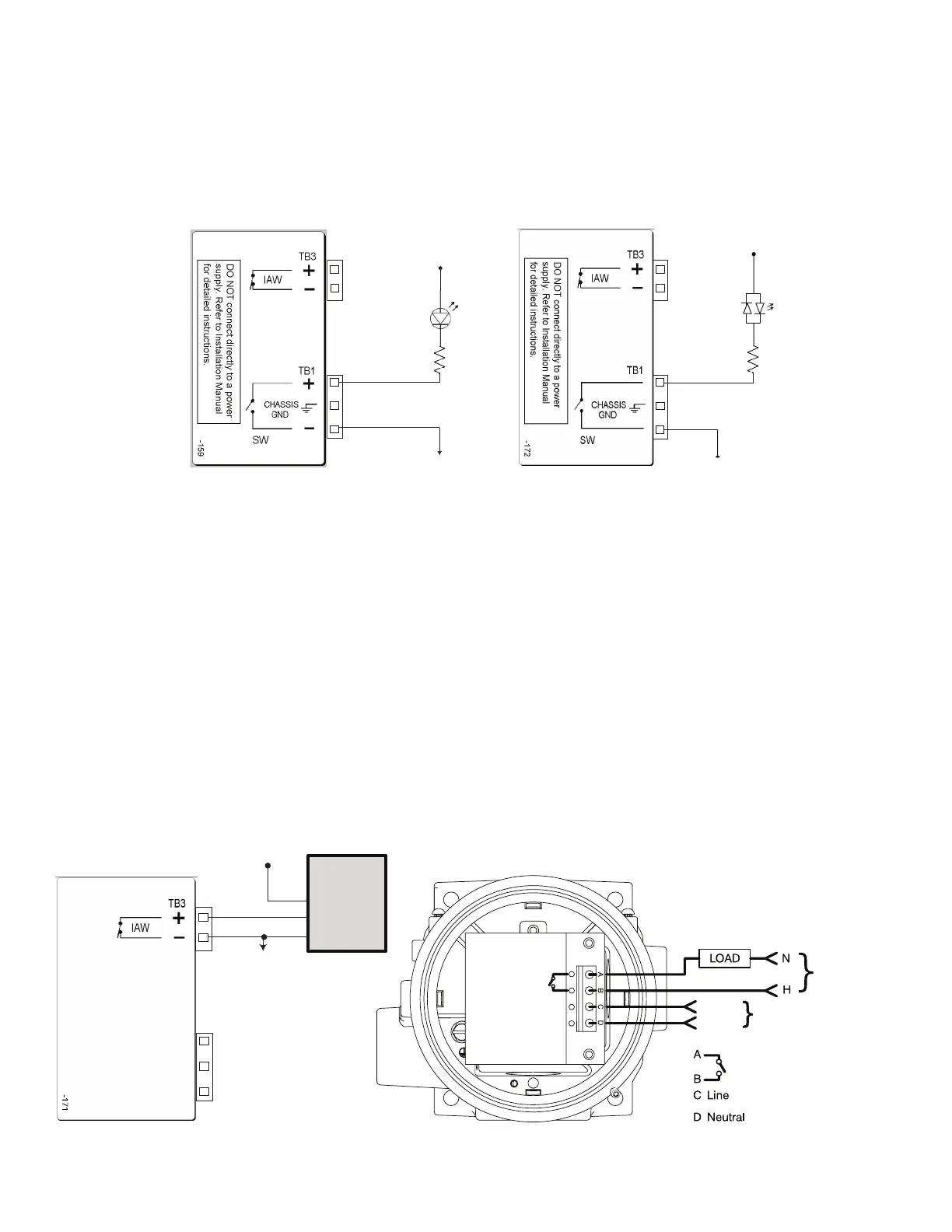
WIRING DIAGRAMS - Model 1XSWHH
Model 1XSWHH requires 70 – 240 VAC @ 0.015 A external power supply for each device. Power for all One Series functions are provided by this
power supply connection at TB2, terminals C (L1/H) and D (L2/N). Connections for the programmable solid state relay switch are made at TB2
terminals A and B. (refer to table 2, page 6 and table 3, page 8).
The wiring diagram below (Figure 9) provides a view inside the One Series base enclosure with the display module removed. TB2 is located there.
All models include a separate IAW
TM
switched output located at TB3 on the back of the display module. This signal provides the health status of
the One Series and is normally closed. When open, this signal provides an indication that IAW
TM
has detected a fault condition. Monitor this signal
by connecting it to the discrete input of a PLC or DCS. The IAW
TM
wiring connection is not required if remote health status of the One Series is not
used.
NOTE: The solid state relay switch in model 1XSWHH has a minimum load requirement of 0.150 A making it incompatible with control system
inputs. Do not exceed the maximum switch ratings (see table 2, page 6) or permanent damage to the One Series may result.
PLC
D
IN
2
PWR
COM
7.8-50 VDC
Common
Base Enclosure
L1/H
L2/N
70-240 VAC
70-240 VAC
0.150-10A MAX
Model
1XSWHH
Load and
Power
Supply Wiring
TB2
1XSWHH
Figure 9
 Loading...