Construcción
ConstrucciónConstrucción
Construcción
49
MK
MK MK
MK STRUCTURE
STRUCTURESTRUCTURE
STRUCTURE
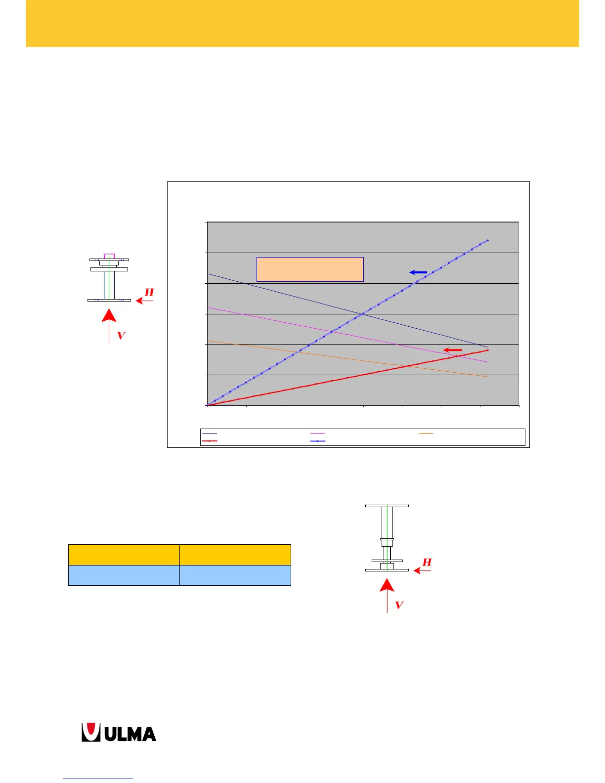
5.1.12. JACK MK 360
The working loads of the Jack MK 360 are indicated in the table below. The table shows the possible combinations
of axial (V) and horizontal (H) forces for the different jack extensions. In the same figure, two straight lines delimit
the values for which there might be a sliding of the nut with respect to the fixed base depending on some
estimated friction coefficients for a nut lubricated or non-lubricated on its base.
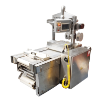
5.1.13. JACK MK 150
The working loads for the JACK MK 150:
V
VV
V
max (SLS)
max (SLS)max (SLS)
max (SLS)
H max (SLS)
H max (SLS)H max (SLS)
H max (SLS)
150 kN
150 kN150 kN
150 kN
8 kN
8 kN8 kN
8 kN
Combinacion AXIL-H ADMISIBLE
PARA EVITAR (DESLIZAMIENTO TUERCA o ROTURA HUSILLO )
0,0
20,0
40,0
60,0
80,0
100,0
120,0
0 50 100 150 200 250 300 350 400
AXIL MAXIMO ADMISIBLE E.L.S.(kN)
H MAXIMO ADMISIBLE E.L.S. (kN)
Extension Husillo 50 Extension Husillo 100 Extension Husillo 200
BASE TUERCA LUBRICADA BASE TUERCA SIN LUBRICAR
POSIBLE DESLIZAMIENTO TUERCA
RESPECTO AL PERFIL HUSILLO EN
FUNCION DEL COEFICIENTE DE
ROZAMIENTO EXISTENTE