Construcción
ConstrucciónConstrucción
Construcción
50
MK
MK MK
MK STRUCTURE
STRUCTURESTRUCTURE
STRUCTURE
5.2.
5.2.5.2.
5.2. LIMITS FOR STANDARD STRUCTURES
LIMITS FOR STANDARD STRUCTURESLIMITS FOR STANDARD STRUCTURES
LIMITS FOR STANDARD STRUCTURES
The following information and data may merely act as reference. Formulas included in different calculation
bases for truss beams are used. They are valid as a first approximation but it is advisable to always verify individually
any truss application.
There are no whatsoever limits for possible truss deformations included herein. Those must be verified with
the help of calculation software for structures.
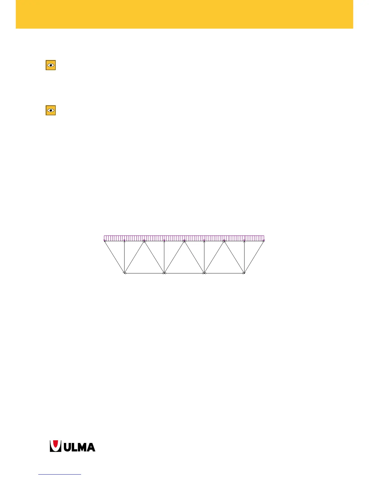
5.2.1. Bi-supported truss structure
This refers to a truss with supports at both ends as shown in the following figure. The spans possible to achieve
with this truss vary depending on the applied modulation. Three load application cases are analysed subsequently:
• As distributed load along the truss
• As point load applied on the centre of the upper boom
• As point loads applied on all nodes of the upper boom
The tables show the maximum permissible load in SLS for each truss (qmax) (Pmax): maximum reaction on prop-
boom joint?, maximum bending moment the truss is able to absorb (M truss max), maximum bending moment in
the waler, maximum axial force in the waler and reactions on the supports depending on the distance between
nodes of the truss.
7.5 7.5 7.5 7.5 7.5 7.5 7.5 7.5