OVERVIEW
- 4 -
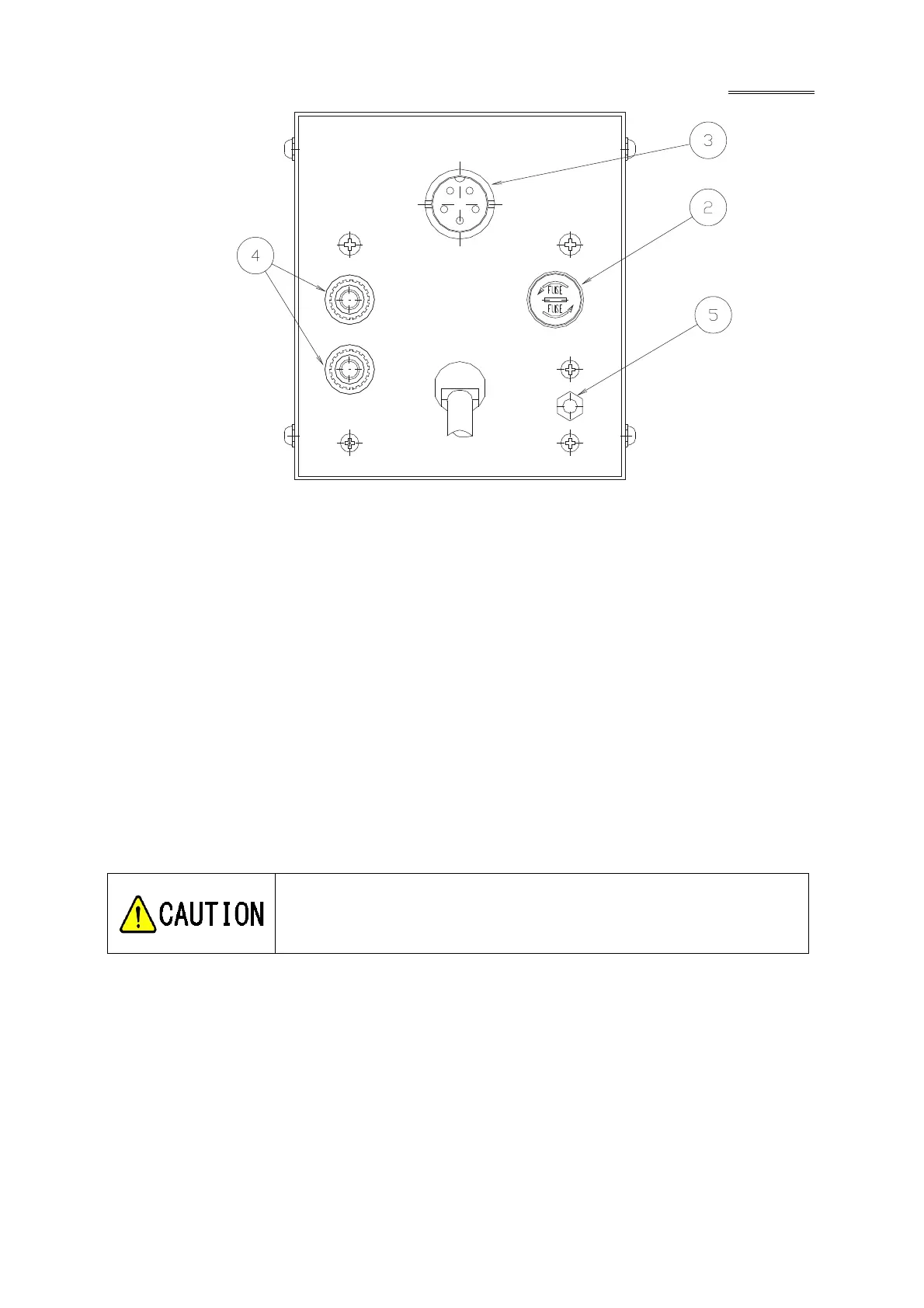
Fig. 2 Rear panel of controller
② Fuse holder
The fuse ampacity is 0.5A.
③ Sensor head connector
Connect to the sensor head cable.
④ Recorder output adjustment ADJ.
The recorder has been factory adjusted to an output voltage of 10 mV with the full scale. If this
value is deviated or if you want to change it, use this ADJ. potentiometer.
[Adjustable range: 0 to 20 mV (with meter full scale)]
⑤ Recorder output terminal: Red terminal (+)
Black terminal (–)
Analog signal is outputted between two terminals.
The recorder output is afloat from ground potential. Always connect the
recorder input to the recorder terminal by insulating it from ground. If it
is connected to GND potential by mistake, the meter will not indicate the correct
value. Also the vacuum gauge may be damaged.


 To Next Page