SK00-4802-DI-002-04
No.16.10.20
41
For ULK-10A,ULK-14A
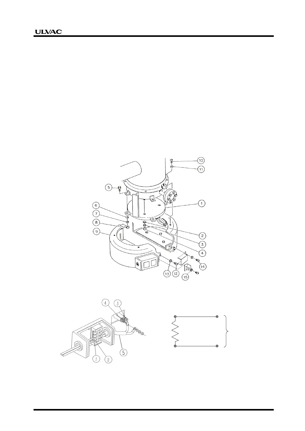
See Figs. 15, 16.
For replacement of the heater, it is necessary to provide a work area with enough volume for that
work. For the volume below the pump, see the external dimensions (Figs. 4, 5).
(1) Figure 16
Remove all connecting terminals for wire connections in the terminal box.
(2) Figure 15
Remove the screws at the top of and before and after the boiler cover, and then remove the
heater cover.
(3) Figure 15
Removal work can be done in the reverse numerical order. Assembling work can be done in
the numerical order.
Also for the removal process of the heater, see the nut numbers shown in Figure 16.
Figure 15: Removal of heater of ULK-10A, ULK-14A
Note: The thermostat is an option.
Figure 16: Wiring work instructions in terminal box for ULK-04A, ULK-06A
①ターミナルボックス内部端子③ヒータ端子
ヒータ源
④ ②
200V 1φ
(220V 1φ)
①ターミナルボックス内部端子③ヒータ端子
ヒータ源
④ ②
200V 1φ
(220V 1φ)
③ Heater terminal
① Terminals in the terminal box
Heater
source